

VFD Braking Resistor Selection: Dynamic Braking Torque, Chopper Rating, Wattage Derating

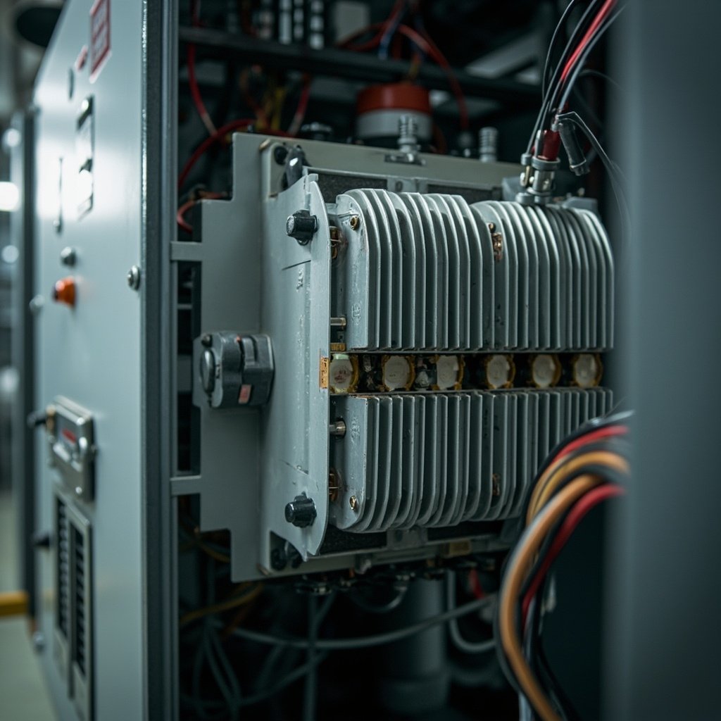
VFD Braking Resistor Selection: Dynamic Braking Torque Calculation, Chopper Transistor Power Rating, Resistor Wattage Derating, Wiring Length Limits, and Overheating Protection Configuration
Introduction
Variable Frequency Drives (VFDs) are widely used in industrial automation to control the speed and torque of electric motors. One of the critical components in VFD systems is the braking resistor, which dissipates the excess energy generated during rapid deceleration or braking of motors. Proper selection of a VFD braking resistor is crucial for ensuring system reliability, efficiency, and safety. This article delves into the technical aspects of VFD braking resistor selection, including dynamic braking torque calculation, chopper transistor power rating, resistor wattage derating, wiring length limits, and overheating protection configuration. We will also explore the selection and installation of inductive proximity sensors, which are vital for monitoring and controlling motor operations.
Dynamic Braking Torque Calculation
Understanding Dynamic Braking
Dynamic braking is the process of using a braking resistor to dissipate the kinetic energy of a motor during deceleration. When a motor is decelerated rapidly, the VFD regenerates energy back into the DC bus. If this energy is not dissipated, it can cause the DC bus voltage to rise, potentially damaging the VFD.
Calculating Braking Torque
The braking torque required can be calculated using the following formula:
\[ T_b = \frac{J \times \Delta \omega}{t} \]
Where:
- \( T_b \) = Braking torque (Nm)
- \( J \) = Moment of inertia of the load and motor (kg·m²)
- \( \Delta \omega \) = Change in angular velocity (rad/s)
- \( t \) = Time for deceleration (s)
For example, if a motor with a moment of inertia of 0.5 kg·m² is decelerated from 1500 rpm to 0 rpm in 5 seconds, the braking torque can be calculated as:
\[ T_b = \frac{0.5 \times (1500 \times \frac{2\pi}{60})}{5} = 15.7 \text{ Nm} \]
Sizing the Braking Resistor
The braking resistor must be capable of handling the power generated during braking. The power can be calculated using:
\[ P = \frac{T_b \times \omega}{9550} \]
Where:
- \( P \) = Power (kW)
- \( \omega \) = Angular velocity (rpm)
For the above example, the power would be:
\[ P = \frac{15.7 \times 1500}{9550} = 2.47 \text{ kW} \]
Chopper Transistor Power Rating
Role of the Chopper Transistor
The chopper transistor in a VFD is responsible for switching the braking resistor in and out of the circuit to control the DC bus voltage. The power rating of the chopper transistor must be sufficient to handle the peak power generated during braking.
Calculating Chopper Transistor Power
The peak power handled by the chopper transistor can be estimated using:
\[ P_{peak} = \frac{V_{dc}^2}{R} \]
Where:
- \( P_{peak} \) = Peak power (W)
- \( V_{dc} \) = DC bus voltage (V)
- \( R \) = Resistance of the braking resistor (Ω)
For instance, with a DC bus voltage of 750 V and a braking resistor of 15 Ω, the peak power would be:
\[ P_{peak} = \frac{750^2}{15} = 37,500 \text{ W} \]
Transistor Selection
The selected transistor must have a power rating higher than the calculated peak power. For example, the Hitachi SJ700-075HFEF2 16228514 Frequency Converter features a robust chopper transistor designed to handle high peak power, making it suitable for demanding applications.
Resistor Wattage Derating
Importance of Derating
Resistor derating is the process of selecting a resistor with a higher power rating than the calculated requirement to ensure longevity and reliability. Environmental factors such as ambient temperature, airflow, and altitude can affect the actual power handling capability of the resistor.
Derating Factor
A typical derating factor is 50%, meaning the resistor’s power rating should be twice the calculated power. For example, if the calculated power is 2.47 kW, the resistor should have a power rating of at least 4.94 kW.
Resistor Selection
When selecting a braking resistor, consider the derated power and the physical size that fits your installation. The Schneider XS508B1PAM8AB Inductive Proximity Sensor M30 can be used to monitor the temperature of the braking resistor, ensuring it does not overheat.
Wiring Length Limits and Considerations
Maximum Cable Length
Standard inductive proximity sensors can operate reliably with a maximum cable length of 100 meters, provided the voltage drop is less than 2V. For longer distances, consider using sensors with higher output current or installing a signal amplifier.
Shielded Cable Usage
Using shielded cables is essential to minimize electromagnetic interference (EMI). The shield should be connected to the controller end only to prevent ground loops. The MURR 4000-68123-0000000 for Control Cabinet Wiring offers excellent EMI protection and is suitable for sensor wiring.
Connector Types
Using M12 connectors can simplify sensor installation and replacement. These connectors are robust and provide reliable connections, reducing the risk of intermittent faults.
Overheating Protection Configuration
Temperature Monitoring
To protect the braking resistor from overheating, install a temperature sensor. The MARPOSS A120 3415159605 Sensor can be used to monitor the temperature and trigger an alarm or shutdown if the temperature exceeds a set threshold.
Thermal Overload Relays
Thermal overload relays can be used to disconnect the braking resistor in case of overheating. The Transformer Cooling Protection with MESSKO MFI100-O Relay is designed for such applications and provides reliable protection.
Ventilation and Heat Dissipation
Ensure that the braking resistor is installed in a well-ventilated area. If necessary, use fans or heat sinks to improve heat dissipation. The mdexx TAM4642-8DD40-0FA0 Transformer AC Control Power can be used to power ventilation systems, ensuring optimal operating conditions.
PNP vs NPN Output Configuration
PNP (Sourcing) Configuration
In a PNP configuration, the sensor outputs a positive voltage when active. The load is connected between the output and 0V. This configuration is commonly used in European machines.
NPN (Sinking) Configuration
In an NPN configuration, the sensor outputs 0V when active. The load is connected between the output and +V. This configuration is typically used in Japanese machines.
Comparison Table
| Feature | PNP (Sourcing) | NPN (Sinking) |
|---|---|---|
| Output when active | Positive voltage | 0V |
| Load connection | Between output and 0V | Between output and +V |
| Common usage | European machines | Japanese machines |
| PLC input module | Must match sensor output type | Must match sensor output type |
| Wiring diagram | Brown=+V, Blue=0V, Black=output | Brown=+V, Blue=0V, Black=output |
Selection Criteria
Choose the configuration that matches your PLC input module. Mixing PNP and NPN on the same input card can lead to malfunction.
Sensor Selection Criteria
Sensing Range (Sn)
The sensing range is the maximum distance at which the sensor can detect a target. According to IEC 60947-5-2, the standard target is a 1mm thick mild steel plate. The actual switching distance depends on the material:
- Steel: 100%
- Stainless steel: 30-70%
- Brass: 25-45%
- Aluminum: 20-40%
- Copper: 15-35%
Sensor Size
Sensor size is chosen based on the application:
- M8 (2mm range): Suitable for small spaces and precise positioning.
- M12 (4mm range): Versatile and commonly used.
- M18 (8mm range): For larger targets and longer ranges.
- M30 (15mm range): For large targets and harsh environments.
Mounting Type
- Flush mounting: The sensor is mounted flush with the mounting surface, reducing the sensing range.
- Non-flush mounting: The sensor protrudes from the mounting surface, increasing the sensing range by 1.5 times.
Mounting Distance Calibration
Parallel Alignment
The sensor face must be parallel to the target surface to ensure reliable detection. Use a feeler gauge for initial gap setting.
Gap Setting
Set the gap to 0.7 times the sensing range (Sn) for reliable detection. For example, if the Sn is 4mm, set the gap to 2.8mm.
Differential Gap Method
For precision positioning, use the differential gap method with two sensors:
- Near limit sensor: Activates when the target is at the near limit.
- Far limit sensor: Activates when the target is at the far limit.
Switching Frequency Verification
Rated Switching Frequency
The rated switching frequency is the maximum frequency at which the sensor can switch on and off at a 50% duty cycle. For example, a typical M12 sensor has a switching frequency of 1000-2500 Hz.
Maximum Frequency Calculation
For counting applications, calculate the maximum frequency using:
\[ f_{max} = \frac{v}{2 \times d} \]
Where:
- \( f_{max} \) = Maximum frequency (Hz)
- \( v \) = Target speed (m/s)
- \( d \) = Sensing range (m)
Verification
If the calculated frequency exceeds the sensor’s rating, the sensor may miss targets. Choose a sensor with a 2x margin above the expected frequency.
EMI Protection and Troubleshooting
EMI Protection
- Keep sensor cables away from VFD output cables (minimum 300mm).
- Use shielded cable with a drain wire.
- Use ferrite rings on cables to reduce EMI.
Troubleshooting
- Check for metallic debris near the sensor face.
- Verify that the target material is ferrous.
- Reduce the sensing range if false triggering occurs.
- Use weld-immune sensors with special face material for welding applications.
Safety Considerations
Safety Devices
The sensor must not be used as a safety device unless it is rated per ISO 13849 (category 1 minimum). For safety interlocking, use dedicated safety sensors with redundant outputs.
Fail-Safe Behavior
Verify that the sensor failsafe behavior is as expected. For PNP sensors, the output should drop to a safe state on wire break.
Maintenance
Cleaning
Clean the sensor face monthly using a non-abrasive cloth. Avoid using solvents on plastic-faced sensors.
Cable Connections
Check cable connections quarterly to ensure they are secure and free from corrosion.
Switching Distance Verification
Verify the switching distance annually to ensure reliable operation.
Replacement
Replace the sensor if the LED indicator flickers or the output voltage drops below specification.
FAQ
Q1: What is the maximum cable length for standard inductive proximity sensors?
The maximum cable length for standard sensors is 100 meters, provided the voltage drop is less than 2V.
Q2: How do I calibrate the mounting distance for an inductive proximity sensor?
Set the gap to 0.7 times the sensing range (Sn) for reliable detection. Use a feeler gauge for initial gap setting.
Q3: What is the difference between PNP and NPN sensors?
PNP sensors output a positive voltage when active, while NPN sensors output 0V when active. The load is connected between the output and 0V for PNP, and between the output and +V for NPN.
Q4: How do I protect the braking resistor from overheating?
Install a temperature sensor and thermal overload relay to monitor and protect the braking resistor from overheating.
Q5: What is the importance of EMI protection for inductive sensors?
EMI protection is crucial to prevent false triggering and ensure reliable operation. Use shielded cables and ferrite rings to minimize EMI.
Conclusion
Selecting the right VFD braking resistor and inductive proximity sensor is vital for the efficient and reliable operation of industrial automation systems. By understanding the technical aspects of braking torque calculation, chopper transistor power rating, resistor derating, wiring length limits, and overheating protection, you can ensure optimal performance. Additionally, proper selection and calibration of inductive proximity sensors will enhance the safety and efficiency of your operations.
Call to Action
Browse our wide range of industrial automation products, including the Hitachi SJ700-075HFEF2 16228514 Frequency Converter, Schneider XS508B1PAM8AB Inductive Proximity Sensor M30, and mdexx TAM4642-8DD40-0FA0 Transformer AC Control Power, to find the perfect components for your needs.