

Schneider Magnetic Contactor Coordination: AC-3 AC-4 Utilization Category, Auxiliary Contact Configuration, Short-Circuit Protection, Contactor Relay Coordination

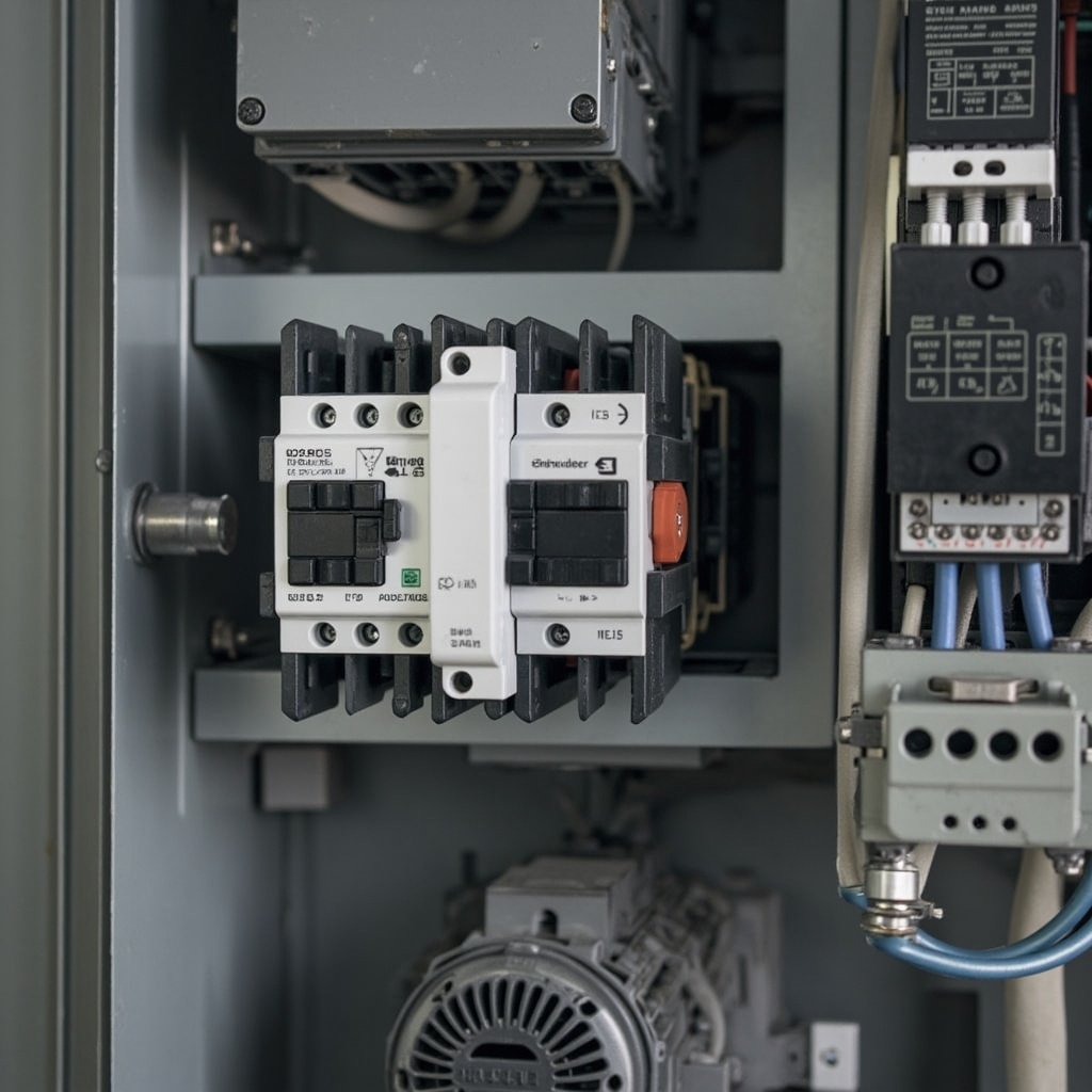
Schneider Magnetic Contactor Coordination: AC-3 AC-4 Utilization Category, Auxiliary Contact Configuration, Short-Circuit Protection, Contactor Relay Coordination
Introduction
Magnetic contactors are the backbone of motor control circuits in industrial applications, enabling the safe and reliable operation of motors, compressors, pumps, and other heavy machinery. These electromechanical switches handle the high currents required for motor starting and stopping, while providing control and protection functions. Proper coordination between the magnetic contactor, thermal overload relay, and short-circuit protection device is crucial for ensuring system reliability, preventing equipment damage, and maintaining personnel safety.
This article focuses on the key aspects of selecting and coordinating Schneider TeSys magnetic contactors for various motor control applications, including motor starting, reversing, star-delta starting, and capacitor switching. We will discuss the following critical topics:
- Utilization Category Selection (AC-3 and AC-4)
- Auxiliary Contact Configuration
- Short-Circuit Protection Coordination
- Thermal Overload Relay Coordination
Our discussion will be based on the IEC 60947 standard framework, which provides guidelines for low-voltage switchgear and controlgear. This article aims to equip electrical panel builders and maintenance engineers with the knowledge needed to select and coordinate Schneider TeSys contactors effectively for their specific applications.
AC-3 and AC-4 Utilization Category Selection
Understanding Utilization Categories
The IEC 60947-4-1 standard defines various utilization categories that specify the operating conditions for contactors based on the type of load they are controlling. For motor control applications, the two most relevant categories are:
- AC-3: This category covers the control of squirrel cage motors during starting and running conditions. It includes the making and breaking of the full-load current of the motor.
- AC-4: This category is for more demanding applications, such as inching (jogging) and plugging, where the contactor is required to make and break the locked-rotor current of the motor repeatedly.
Key Selection Criteria
When selecting a contactor for motor control, consider the following parameters:
- Rated Operational Current (Ie): This is the maximum current the contactor can carry continuously under specified conditions. For example, the Schneider LC1DWK12P7 Magnetic Contactor has a rated operational current of 12A for AC-3 applications.
- Rated Making Capacity (Icm): This is the maximum current the contactor can make at the rated voltage. For the LC1DWK12P7, this value is 170A.
- Rated Breaking Capacity (Icu): This is the maximum current the contactor can break at the rated voltage. The LC1DWK12P7 has a rated breaking capacity of 170A.
- Contact Life Expectancy: The number of operating cycles the contactor can perform under specific load conditions. For AC-3 applications, the LC1DWK12P7 has a life expectancy of 1.2 million cycles.
Derating for Switching Frequency
For applications with high switching frequencies, such as frequent starts and stops, it is important to derate the contactor to ensure it does not overheat. The derating factor depends on the switching frequency and the utilization category. For example, for a switching frequency of 300 operations per hour, the LC1DWK12P7 may need to be derated by 10%.
Application Examples
- AC-3: Suitable for most motor starting applications, such as pumps, fans, and compressors. For instance, the Schneider ATV32H037N4 VFD can be paired with the LC1DWK12P7 for controlling a 5.5 kW motor in an AC-3 application.
- AC-4: Ideal for applications requiring frequent starts, stops, and reversals, such as cranes, hoists, and conveyor systems.
Auxiliary Contact Configuration
NO and NC Contact Arrangements
Auxiliary contacts are used for control and indication purposes. They are available in two configurations:
- Normally Open (NO): Contacts that are open when the contactor is de-energized and close when the contactor is energized.
- Normally Closed (NC): Contacts that are closed when the contactor is de-energized and open when the contactor is energized.
Auxiliary Contact Block Mounting
Schneider TeSys contactors offer flexible mounting options for auxiliary contact blocks. They can be mounted on the front or side of the contactor, depending on the model. For example, the LC1DWK12P7 can accommodate up to 4 auxiliary contacts.
Mirror Contact for Safety Indication
Mirror contacts provide a safety indication function. They are mechanically linked to the main contacts and change state when the main contacts change state. This ensures that the indication is reliable and cannot be tampered with.
Forced-Guided Contact per IEC 60947-5-1
Forced-guided contacts are designed to prevent dangerous situations by ensuring that the NO and NC contacts cannot be in the same state simultaneously. This is particularly important for safety-critical applications.
Auxiliary Contact Ratings
Auxiliary contacts have different ratings depending on the application:
- AC-15: Suitable for controlling electromagnetic loads, such as contactors and control relays.
- DC-13: Suitable for controlling resistive loads and DC electromagnets.
For example, the LC1DWK12P7 has auxiliary contacts rated for 6A at 240V AC-15 and 2A at 110V DC-13.
Application Examples
- PLC Input: Auxiliary contacts can be used to provide feedback to a PLC for monitoring the status of the contactor.
- Indication Lamp Circuit: NO contacts can be used to control an indication lamp to show that the contactor is energized.
- Interlocking Contact for Reverse: NC contacts can be used to prevent reverse operation when the contactor is energized.
Short-Circuit Protection Coordination
Fuse Type Selection
For short-circuit protection, fuses are commonly used. The two main types are:
- gG: General purpose fuses suitable for both short-circuit and overload protection.
- aM: Motor-rated fuses designed to withstand the high inrush currents associated with motor starting.
Circuit Breaker Magnetic Setting
Circuit breakers can also be used for short-circuit protection. The magnetic setting should be set to a value that will trip the circuit breaker quickly in the event of a short circuit, but not trip during normal motor starting.
Type 1 vs Type 2 Coordination
The IEC 60947-4-1 standard defines two types of coordination:
- Type 1: The contactor and overload relay may be damaged in the event of a short circuit, but there is no risk of fire or explosion.
- Type 2: The contactor and overload relay must not be damaged in the event of a short circuit, and the contacts must remain closed.
Type 2 coordination is preferred for most applications as it provides better protection and reduces the risk of downtime.
Let-Through Energy (I2t)
The let-through energy is the amount of energy that passes through the protective device during a short circuit. It is important to ensure that the contactor can withstand the let-through energy of the protective device.
Short-Circuit Test Procedure
Short-circuit testing is performed to verify the coordination between the contactor and the protective device. The test involves applying a short circuit to the circuit and observing the behavior of the contactor and protective device.
Protective Device Rating Selection
The rating of the protective device should be selected based on the motor full-load current (FLA) and the type of coordination required. For example, for a motor with an FLA of 10A, a gG fuse with a rating of 16A or an aM fuse with a rating of 25A might be used.
Thermal Overload Relay Coordination
Bimetallic vs Electronic Overload Relay
Thermal overload relays are available in two types:
- Bimetallic: Uses a bimetallic strip that bends in response to heat, causing the relay to trip.
- Electronic: Uses electronic circuitry to monitor the current and trip the relay when the current exceeds a set value.
Electronic overload relays offer more precise protection and additional features, such as adjustable trip classes and phase loss detection.
Trip Class Selection
The trip class determines the time it takes for the relay to trip when the current exceeds the set value. Common trip classes are 10, 20, and 30. A lower trip class provides faster protection.
Setting Current Adjustment
The setting current should be adjusted to match the motor FLA. This ensures that the relay will trip when the motor is overloaded.
Ambient Temperature Compensation
Some overload relays have ambient temperature compensation to ensure reliable operation in different temperature conditions.
Phase Loss Detection
Electronic overload relays can detect phase loss, which is important for protecting the motor from damage.
Auto Manual Reset
Overload relays can be set to auto or manual reset. Auto reset is convenient, but manual reset provides better safety as it requires an operator to check the cause of the overload before resetting.
Test Trip Function
A test trip function allows the relay to be tested without interrupting the motor operation.
Comparison Table: Schneider TeSys Contactor Selection Parameters
| Model | Rated Current (A) | Utilization Category | Auxiliary Contact Options | Coil Voltage Range (V) | Typical Application |
|---|---|---|---|---|---|
| LC1DWK12P7 | 12 | AC-3, AC-4 | 4 NO/NC | 24-400 | Motor starting, reversing |
| LC1D12P7 | 12 | AC-3 | 2 NO/NC | 24-400 | General purpose motor control |
| LC1D18P7 | 18 | AC-3 | 2 NO/NC | 24-400 | Motor control with higher current |
| LC1D25P7 | 25 | AC-3 | 2 NO/NC | 24-400 | Motor control with higher current |
FAQ
1. What is the difference between AC-3 and AC-4 utilization categories?
AC-3 is for controlling squirrel cage motors during starting and running, while AC-4 is for more demanding applications, such as inching and plugging, where the contactor makes and breaks the locked-rotor current repeatedly.
2. How do I select the right auxiliary contact configuration?
The auxiliary contact configuration depends on the control and indication requirements of your application. Consider the number of NO and NC contacts needed, the mounting options, and the ratings of the contacts.
3. What is the difference between Type 1 and Type 2 coordination?
Type 1 allows for damage to the contactor and overload relay in the event of a short circuit, while Type 2 requires that the contactor and relay remain undamaged. Type 2 is preferred for most applications as it provides better protection.
Conclusion
Proper coordination between the magnetic contactor, thermal overload relay, and short-circuit protection device is essential for the reliable and safe operation of motor control circuits. By understanding the utilization categories, auxiliary contact configurations, and protection coordination principles, engineers can select the right Schneider TeSys contactors for their specific applications.
For more information on Schneider TeSys contactors and related products, visit Schneider LC1DWK12P7 Magnetic Contactor, Schneider ATV32H037N4 VFD, and Schneider XS508B1PAM8AB Inductive Proximity Sensor.
