Schneider ATV310 VFD Commissioning: Motor Nameplate Parameter Entry, Speed Reference Channel, PID Regulator Tuning, Modbus RTU Communication Configuration

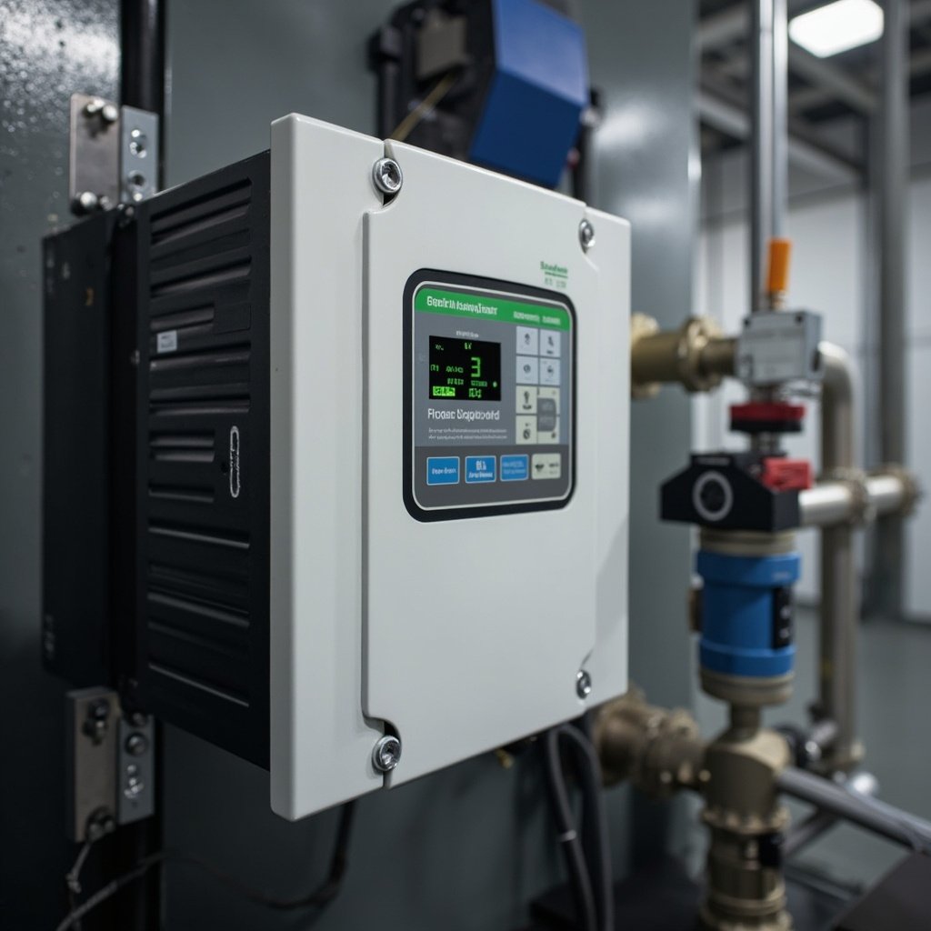
Schneider ATV310 VFD Commissioning: Motor Nameplate Parameter Entry, Speed Reference Channel, PID Regulator Tuning, Modbus RTU Communication Configuration
Introduction
The Schneider Electric ATV310 series of variable frequency drives (VFDs) is specifically designed for commercial building HVAC systems, industrial pump and fan applications, and simple motion control tasks. As a compact, versatile, and energy-efficient VFD, the ATV310 offers advanced motor control capabilities while maintaining ease of use for commissioning engineers.
Compared to its predecessor, the ATV32, the ATV310 provides enhanced features including improved energy efficiency, expanded communication options, and more sophisticated control functions. Proper commissioning of the ATV310 is crucial for achieving optimal energy efficiency, reliable process control, and maximum equipment lifespan in applications such as HVAC fan control, pump speed regulation, and conveyor systems.
This article provides a comprehensive guide for electrical technicians and HVAC engineers on commissioning the Schneider ATV310 VFD, focusing on:
- Motor nameplate parameter entry and auto-tuning procedures
- Speed reference channel and running command configuration
- PID regulator configuration and auto-tuning for process control
- Modbus RTU communication setup and integration
By following this commissioning guide, engineers can ensure the ATV310 operates efficiently and reliably in various applications, including those using the Schneider ATV310H075N4A VFD (https://ai-electrical.com/products/factory-hvac-and-pump-control-using-schneider-atv310h075n4a/).
Motor Nameplate Parameter Entry and Auto-Tuning
Entering Motor Parameters
Accurate motor parameter entry is essential for the ATV310 to operate the motor safely and efficiently. The following parameters must be entered from the motor nameplate:
- Rated Voltage (Un): The motor’s nominal operating voltage (e.g., 380-480V)
- Rated Current (In): The motor’s nominal operating current
- Rated Frequency (Fn): Typically 50Hz or 60Hz
- Rated Speed (Nn): The motor’s nominal speed in RPM
- Rated Power (Pn): The motor’s nominal power in kW or HP
Additionally, the motor thermal current (ItH) parameter must be set to protect the motor from overheating. This value is usually 10-15% higher than the rated current.
Stator Resistance Measurement
For optimal motor control, especially in sensorless vector control mode, the ATV310 can measure the stator resistance (Rs). This parameter can be measured automatically using the drive’s built-in functions or entered manually if known.
Auto-Tuning Procedure
The ATV310 offers two auto-tuning procedures:
- Stationary Auto-Tuning: This method measures motor parameters without rotating the motor. It is suitable for applications where rotating the motor is not possible or desirable.
- Rotating Auto-Tuning: This method provides more accurate motor parameter identification by rotating the motor at a low speed. It is recommended for applications requiring precise torque control.
Scalar Control (U/f) vs. Sensorless Vector Control
- Scalar Control (U/f): This mode is suitable for simple applications where precise speed control is not critical. It is easy to set up but offers limited performance compared to vector control.
- Sensorless Vector Control: This mode provides better dynamic performance, torque control, and energy efficiency. It is recommended for applications requiring precise speed regulation, such as HVAC fans and pumps.
Motor Slip Compensation
The ATV310 can compensate for motor slip, which is the difference between the synchronous speed and the actual rotor speed. This feature improves speed regulation accuracy, particularly at low speeds.
Flux Braking Function
The ATV310 includes a flux braking function that allows for rapid deceleration of the motor by applying a braking torque. This is useful in applications where quick stops are required, such as conveyor systems.
Energy Saving Mode Activation
The ATV310 features an energy-saving mode that optimizes the motor’s magnetic flux based on the load. This reduces energy consumption, particularly in applications with variable torque loads, such as pumps and fans.
Speed Reference Channel and Running Command Configuration
Speed Reference Channels
The ATV310 supports multiple speed reference channels, allowing for flexible control strategies:
- AI1 Analog Input (0-10V): This input can be used for speed reference when using a 0-10V signal from a controller or potentiometer.
- AI2 Analog Input (0-20mA/4-20mA): This input is suitable for current-based speed reference signals, commonly used in process control applications.
- AI1+AI2 Dual Channel: The ATV310 can combine AI1 and AI2 inputs using sum or switch functions, providing redundancy or more complex control schemes.
- Modbus RTU Communication: The ATV310 can receive speed reference commands via Modbus RTU communication, enabling integration with PLCs and SCADA systems.
Running Command Configuration
The ATV310 offers flexible running command options:
- Terminal Logic Inputs (LI1-LI6): These inputs can be configured for forward, reverse, start, stop, and other control functions.
- 2-Wire Control: Uses a single input for start/stop and another for direction.
- 3-Wire Control: Uses separate inputs for start, stop, and direction.
Speed Reference Scaling and Ramps
The ATV310 allows for scaling the speed reference to set the minimum and maximum frequencies. Additionally, the acceleration and deceleration ramps can be adjusted to ensure smooth starts and stops, protecting the mechanical system from sudden changes in speed.
PID Regulator Configuration and Auto-Tuning
Internal PID Controller
The ATV310 includes an internal PID regulator for process control applications. The PID controller can regulate process variables such as pressure, flow, or temperature by adjusting the motor speed.
Feedback Signal Assignment
The feedback signal for the PID controller can be assigned to:
- AI1 or AI2 Analog Inputs: For receiving feedback from sensors such as pressure transducers or flow meters.
- Schneider XS508B1PAM8AB Inductive Proximity Sensor (https://ai-electrical.com/products/schneider-xs508b1pam8ab-inductive-proximity-sensor-m30/): For detecting the position or speed of moving parts.
Setpoint Source
The PID setpoint can be configured from:
- Analog Input: Using a potentiometer or external controller.
- Modbus RTU Communication: Allowing for remote setpoint adjustment via PLC or SCADA.
PID Tuning Parameters
The ATV310’s PID regulator has the following adjustable parameters:
- Proportional Gain (Kp): Determines the controller’s response to the error.
- Integral Time (Ti): Determines the controller’s response to accumulated error.
- Derivative Time (Td): Determines the controller’s response to the rate of change of error.
PID Auto-Tuning Function
The ATV310 features a PID auto-tuning function that simplifies the process of setting PID parameters. This function is particularly useful for pump and fan applications, where the system dynamics can be complex.
Sleep and Wake Function
For applications with variable torque loads, the ATV310 includes a sleep and wake function. This feature reduces energy consumption by stopping the motor when the process variable is within a specified range and starting it again when needed.
PID Reverse Action
The ATV310 can be configured for reverse action, which is useful for applications such as cooling tower fans, where the control logic needs to be inverted.
Cascade Control and Multi-Pump Switching
The ATV310 supports cascade control and multi-pump switching, allowing for the coordinated operation of multiple pumps or fans. This feature is beneficial for maintaining system redundancy and optimizing energy efficiency.
Modbus RTU Communication and ATV310 Network Setup
RS-485 Wiring
The ATV310 communicates via Modbus RTU over an RS-485 serial connection. The following connections are required:
- AI+ (D+): Data line positive
- AI- (D-): Data line negative
- GND: Ground
Modbus Address Setting
Each ATV310 on the network must be assigned a unique Modbus address (1-247). This address is used to identify the device on the network.
Baud Rate and Parity
The ATV310 supports the following Modbus RTU communication parameters:
- Baud Rate: 9600, 19200, 38400
- Parity: Even, Odd, None
Modbus Register Map
The ATV310 has a comprehensive Modbus register map that allows for reading and writing of drive parameters, including speed reference, output frequency, and status information.
Integration with PLC and SCADA Systems
The ATV310 can be integrated with PLCs and SCADA systems using Modbus RTU. This enables remote monitoring and control of the drive, providing greater flexibility in system design and operation.
Modbus Communication Troubleshooting
Common issues with Modbus RTU communication include:
- Incorrect Wiring: Verify all connections are secure and correct.
- Address Conflict: Ensure each device on the network has a unique address.
- Parameter Mismatch: Verify baud rate and parity settings match between devices.
- Noise: Use shielded cables and proper grounding to minimize electrical noise.
Comparison Table: Schneider ATV310 vs ATV32 vs Competing HVAC VFDs
| Feature/Parameter | Schneider ATV310 | Schneider ATV32 | Competitor A | Competitor B |
|---|---|---|---|---|
| Power Range | 0.37-75kW | 0.18-75kW | 0.37-500kW | 0.25-450kW |
| PID Function | Yes | Yes | Yes | Yes |
| Communication Protocol | Modbus RTU, Modbus TCP | Modbus RTU, Modbus TCP | Modbus RTU, Profibus | Modbus RTU, Ethernet/IP |
| Protection Class | IP20, IP54 | IP20, IP54 | IP20, IP54 | IP20, IP54 |
| Typical Application | HVAC, Pumps, Fans | HVAC, Pumps, Fans | Industrial Motors | Commercial Buildings |
| Energy Efficiency | High | Medium | High | Medium |
| Sensorless Vector Control | Yes | Yes | Yes | Yes |
| Multi-Pump Control | Yes | No | Yes | No |
| Sleep/Wake Function | Yes | No | Yes | No |
FAQ
Q1: Can the ATV310 be used in applications requiring precise torque control?
Yes, the ATV310 supports sensorless vector control, which provides precise torque control suitable for demanding applications.
Q2: How does the ATV310 handle motor overheating?
The ATV310 monitors the motor thermal current (ItH) and can trigger an alarm or shutdown if overheating is detected.
Q3: Can the ATV310 be integrated with Schneider’s SCADA systems?
Yes, the ATV310 can be integrated with Schneider’s SCADA systems using Modbus RTU or Modbus TCP protocols.
Conclusion
The Schneider ATV310 VFD offers a comprehensive solution for HVAC, pump, and fan applications, combining advanced motor control capabilities with energy-efficient operation. Proper commissioning, including accurate parameter entry, speed reference configuration, PID regulator tuning, and Modbus RTU communication setup, is essential for optimal performance.
By following the guidelines outlined in this article, engineers can ensure the ATV310 operates reliably and efficiently in various commercial and industrial applications. For more information on the ATV310H075N4A VFD, visit https://ai-electrical.com/products/factory-hvac-and-pump-control-using-schneider-atv310h075n4a/.
Call to Action: Explore our range of Schneider VFDs and accessories, including the ATV310H075N4A VFD (https://ai-electrical.com/products/factory-hvac-and-pump-control-using-schneider-atv310h075n4a/) and Schneider XS508B1PAM8AB Inductive Proximity Sensor (https://ai-electrical.com/products/schneider-xs508b1pam8ab-inductive-proximity-sensor-m30/), to find the right solution for your automation needs.