

Electromagnetic Flow Meter Installation: Electrode Orientation, Grounding, Liner, Calibration

Comments Off on Electromagnetic Flow Meter Installation: Electrode Orientation, Grounding, Liner, Calibration
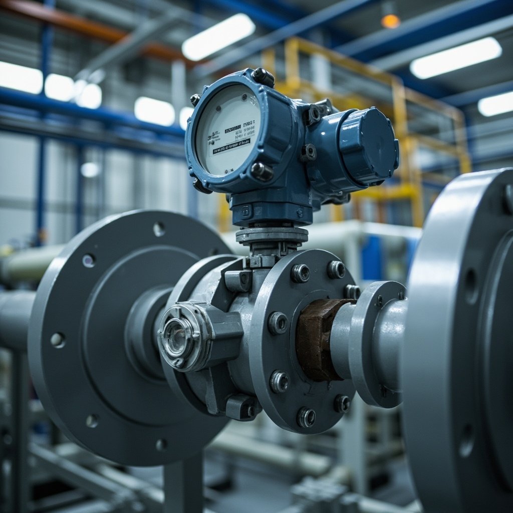
Electromagnetic Flow Meter Installation: Electrode Orientation, Grounding Ring Selection, Pipe Liner Compatibility, Signal Cable Length, and Calibration Verification for Process Applications
Electromagnetic flow meters, also known as mag meters, are crucial instruments in industrial process applications for measuring the flow rate of conductive liquids. Their non-intrusive design, high accuracy, and reliability make them ideal for various industries, including water treatment, chemical processing, food and beverage, and pharmaceuticals. Proper installation and calibration of these meters are essential to ensure accurate and consistent measurements. This article delves into the critical aspects of electromagnetic flow meter installation, including electrode orientation, grounding ring selection, pipe liner compatibility, signal cable routing, and calibration verification. We will also reference specific products available on our platform to provide practical insights.
Operating Principle: Faraday’s Law in Action
The operation of electromagnetic flow meters is based on Faraday’s Law of Electromagnetic Induction. According to this principle, when a conductive liquid flows through a magnetic field, a voltage is induced across the liquid that is proportional to the flow velocity. The mathematical expression for this is:
\[ E = B \times D \times v \]
Where:
- \( E \) = Induced voltage
- \( B \) = Magnetic field strength
- \( D \) = Distance between electrodes (inner diameter of the pipe)
- \( v \) = Average fluid velocity
The volumetric flow rate \( Q \) is then calculated as:
\[ Q = v \times A \]
Where \( A \) is the cross-sectional area of the pipe.
Conductivity Requirements
For standard electromagnetic flow meters, the minimum conductivity of the fluid should be greater than 5 microSiemens/cm. However, for capacitive electrode types, this requirement is significantly lower, typically greater than 0.1 microSiemens/cm. This makes capacitive meters suitable for applications involving low-conductivity fluids, such as deionized water.
Electrode Orientation: Ensuring Accurate Measurements
The orientation of the electrodes in an electromagnetic flow meter is critical for accurate measurements, especially in applications involving slurries or fluids with suspended solids.
Clean Liquids
For clean liquids, it is recommended to install the meter with the electrodes in the horizontal position (3 and 9 o’clock). This ensures that the electrodes are always submerged, providing a consistent and reliable measurement. For instance, the GEMU 857R15D7R2114 Flow Meter for Industrial Process is designed with this orientation in mind, ensuring optimal performance in clean liquid applications.
Slurries and Suspensions
When dealing with slurries or fluids with suspended solids, it is advisable to install the meter with the electrodes at a 45-degree angle. This orientation prevents sediment buildup on the lower electrode, which can lead to inaccurate readings. The angled position allows the solids to flow past the electrodes without settling, maintaining the integrity of the measurement.
Vertical Pipes
In vertical pipe installations, the flow must be directed upward to ensure the pipe remains full. This prevents the formation of air pockets, which can cause signal loss and measurement errors. For applications involving pumps, it is crucial to install a pulsation dampener to reduce flow ripple and ensure steady flow conditions.
Grounding Ring Selection: Ensuring Electrical Continuity
Grounding rings are essential components in electromagnetic flow meter installations as they ensure electrical contact between the fluid and the meter’s ground potential. The choice of grounding ring material is critical and should be based on the pipe material and the corrosivity of the fluid.
Material Selection
The following table provides guidance on selecting the appropriate grounding ring material based on the application:
| Fluid Type | Recommended Grounding Ring Material |
|---|---|
| Water, Mild Chemicals | 316 Stainless Steel |
| Strong Acids, Chlorides | Hastelloy C |
| Seawater, Hypochlorite | Titanium |
| Concentrated Acids | Tantalum |
| High-Purity Water | Platinum |
For non-metallic pipes, such as those lined with PTFE, FRP, or PVC, grounding rings are mandatory to establish the necessary electrical contact.
Product Example
The REXROTH R106522000 Vibration Sensor Industrial Monitoring can be used in conjunction with the appropriate grounding ring to ensure optimal performance in challenging environments.
Pipe Liner Compatibility: Choosing the Right Material
The pipe liner is another critical component that affects the performance of electromagnetic flow meters. The liner material must be compatible with the process fluid and the operating temperature.
Common Liner Materials
- PTFE (Polytetrafluoroethylene): Known for its excellent chemical resistance and wide temperature range (-25 to +150°C), PTFE is ideal for corrosive liquids. It is commonly used in applications involving strong acids and alkalis.
- Polyurethane: This material offers high abrasion resistance, making it suitable for slurries and mining applications. It is also flexible and can withstand mechanical stress.
- Rubber (Natural or Synthetic): Rubber liners are cost-effective and provide good resistance to water and wastewater. They are ideal for applications where cost is a concern.
- Ceramic: Ceramic liners are used in high-temperature applications exceeding 200°C. They offer excellent resistance to thermal shock and chemical attack.
Verification and Maintenance
It is essential to verify that the chosen liner is compatible with the process fluid and operating conditions. A damaged liner can cause measurement errors and expose the electrodes to the fluid, leading to potential corrosion and fouling.
Signal Cable Length and Routing: Ensuring Signal Integrity
The signal cable connecting the flow meter to the transmitter is crucial for maintaining signal integrity. The following guidelines should be followed:
Cable Length
- Standard Length: The maximum length for a standard transmitter-to-sensor cable is 100 meters. This is typically sufficient for most industrial applications.
- Extended Range: For applications requiring longer distances, a separate converter unit can extend the range up to 300 meters.
Cable Routing
- Avoid Coiling: Excess cable should not be coiled, as this can create inductance and affect the signal.
- Separation from Power Cables: The signal cable should be routed away from power cables and VFD output cables, with a minimum separation of 300 mm to minimize electromagnetic interference (EMI).
- Outdoor Installation: For outdoor installations, use a junction box with an IP67 rating to protect the connections from environmental factors.
Product Example
The REXROTH R151217052 Roller Bearing Industrial Motion can be used in conjunction with the appropriate signal cable to ensure reliable performance in industrial settings.
Calibration Verification: Ensuring Accuracy
After installation, it is essential to verify the calibration of the electromagnetic flow meter to ensure accurate measurements. The following methods can be used:
Comparison with Reference Meter
- Method: Install a calibrated reference meter in series with the electromagnetic flow meter.
- Procedure: Compare the readings at multiple flow rates to ensure consistency.
- Advantage: Provides real-time verification and is suitable for continuous process monitoring.
Gravimetric Method
- Method: Collect the fluid over a timed interval and weigh it on a calibrated scale.
- Procedure: Compare the measured weight to the flow meter reading.
- Advantage: Highly accurate and suitable for verifying meter accuracy.
Manufacturer Factory Calibration Certificate
- Method: Refer to the manufacturer’s factory calibration certificate, which is traceable to national standards.
- Procedure: Ensure the meter is operating within the specified accuracy, typically ±0.5% of rate or ±0.2% for high-precision meters.
- Advantage: Provides a reliable baseline for calibration verification.
Field Calibration Adjustment
- Method: Adjust the span and zero settings via the transmitter menu.
- Procedure: Use the manufacturer’s guidelines to fine-tune the calibration.
- Advantage: Allows for minor adjustments to improve accuracy.
Comparison Table
| Method | Advantages | Disadvantages |
|---|---|---|
| Reference Meter Comparison | Real-time verification, suitable for continuous monitoring | Requires additional equipment, may disrupt process |
| Gravimetric Method | Highly accurate, direct measurement | Time-consuming, requires process interruption |
| Factory Calibration Certificate | Reliable, traceable to national standards | May not account for installation conditions |
| Field Calibration Adjustment | Allows for minor adjustments, improves accuracy | Requires expertise, may not be suitable for all meters |
Installation Requirements: Ensuring Optimal Performance
Proper installation is crucial for the optimal performance of electromagnetic flow meters. The following guidelines should be followed:
- Straight Pipe Length: Ensure a minimum upstream straight pipe length of 5 times the pipe diameter (5x DN) and a minimum downstream length of 2x DN. For disturbed flow profiles caused by valves or elbows, increase the upstream length to 10x DN.
- Pulsation Dampener: For pump discharge installations, install a pulsation dampener to reduce flow ripple.
- Pipe Fullness: Ensure the pipe is always full during operation. Install the meter on a downward sloping pipe or vertically with upward flow.
- Isolation Valves: Install isolation valves upstream and downstream for maintenance access.
Troubleshooting Common Issues: Ensuring Reliability
Zero Instability
- Cause: Electrode condition, pipe fullness, grounding.
- Solution: Check electrode condition, verify the pipe is full, check grounding.
No Flow Indication
- Cause: Electrode connections, fluid conductivity, transmitter power supply.
- Solution: Check electrode connections, verify fluid conductivity is above the minimum, check transmitter power supply.
Erratic Readings
- Cause: Air bubbles in fluid, cable shielding, EMI from nearby equipment.
- Solution: Check for air bubbles in the fluid, verify cable shielding, check for EMI from nearby equipment.
High Measurement Error
- Cause: Liner condition, calibration, electrode coating or fouling.
- Solution: Check liner condition, verify calibration, check for electrode coating or fouling.
Conclusion
Proper installation and calibration of electromagnetic flow meters are essential for accurate and reliable measurements in industrial process applications. By following the guidelines outlined in this article, you can ensure optimal performance and longevity of your flow meters. For more information on specific products, such as the GEMU 857R15D7R2114 Flow Meter for Industrial Process, please visit our website and browse our range of industrial automation solutions.
Call to Action
Browse our range of electromagnetic flow meters and related products to find the perfect solution for your industrial process application. Whether you need a REXROTH R106522000 Vibration Sensor Industrial Monitoring or a Machine Monitoring with MARPOSS 3CRJK9 3045548507, our selection caters to a wide array of industrial needs. Start exploring today and enhance the efficiency and accuracy of your operations.