

Proportional Valve Control: A Complete Guide to Principles, Applications, and Best Practices

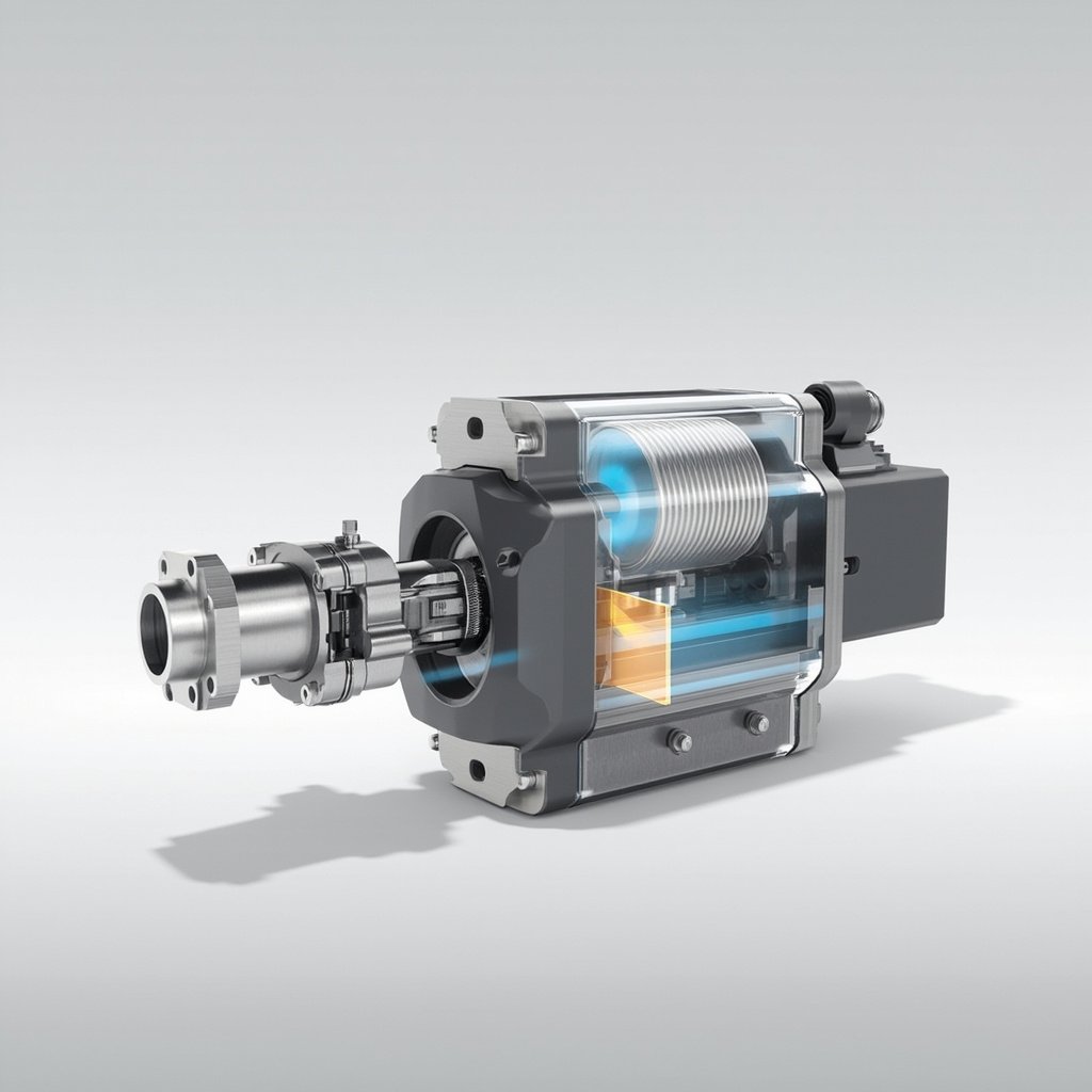
Proportional valve control is a fundamental technology in modern hydraulic and pneumatic systems, enabling precise regulation of fluid flow, pressure, and direction based on electronic input signals. Unlike traditional on/off valves that operate in binary states, proportional valves offer infinitely variable control, allowing operators to fine-tune system parameters for optimal performance. This advanced control methodology is widely used in industries ranging from manufacturing and automation to mobile equipment and aerospace, where precision, efficiency, and repeatability are critical operational requirements.
The core principle behind proportional valve control involves the use of an electronic signal—typically a current ranging from 4 to 20 mA or a voltage from 0 to 10 V—to position a spool or poppet within the valve body. This positioning determines the size of the flow path, directly controlling the rate of fluid passage. As the input signal increases or decreases, the valve opening adjusts proportionally, providing smooth, continuous modulation rather than abrupt changes. This characteristic makes proportional valves indispensable in applications demanding accurate motion control, force regulation, and energy-efficient operation.
How Proportional Valve Control Works
The operational foundation of a proportional valve relies on the integration of mechanical, hydraulic, and electronic components working in harmony. At the heart of the system is a solenoid actuator or torque motor that receives electrical signals from a controller, such as a PLC (Programmable Logic Controller) or dedicated motion controller. The controller interprets commands and sends appropriate current or voltage levels to the valve’s electromagnetic coil.
When the coil is energized, it generates a magnetic field that moves a ferromagnetic armature connected to the valve spool. The spool shifts in proportion to the applied signal strength, opening or restricting the flow passages. A position feedback sensor—often an LVDT (Linear Variable Differential Transformer) or Hall effect sensor—monitors the actual spool position and sends this data back to the controller. This closed-loop feedback system ensures the spool reaches and maintains the precise position demanded by the input signal, compensating for disturbances such as load changes, pressure fluctuations, and temperature variations.
Key Components of a Proportional Valve System
- Electronic Controller: The brain of the system, typically a PLC, microcontroller, or motion controller that generates the command signal based on operational requirements.
- Proportional Solenoid: Converts electrical energy into proportional mechanical force that positions the valve spool.
- Valve Spool or Poppet: The moving element that regulates fluid flow by varying the size of the flow orifice.
- Position Feedback Sensor: Provides real-time data about the actual spool position, enabling closed-loop control and high accuracy.
- Hydraulic or Pneumatic Actuator: The cylinder or motor whose motion is being controlled by the valve.
- Power Supply: Provides stable, regulated current to the proportional solenoid for consistent performance.
Types of Proportional Valves
Proportional valves are categorized based on their function, design, and the parameter they control. Understanding the differences between these types helps engineers select the most appropriate component for specific applications.
1. Proportional Directional Control Valves
These valves control the direction and magnitude of fluid flow to actuators. They feature multiple ports and positions, allowing for bidirectional motion control. By varying the input signal, operators can achieve smooth acceleration, deceleration, and reversal of hydraulic cylinders or motors.
2. Proportional Pressure Control Valves
These valves regulate system pressure in proportion to the input signal. They are commonly used to maintain constant pressure under varying load conditions, control clamping forces, and manage accumulator charging.
3. Proportional Flow Control Valves
Designed to regulate flow rate independently of pressure variations, these valves are essential in applications requiring precise speed control of hydraulic actuators.
Applications Across Industries
Proportional valve control technology has transformed numerous industrial sectors by providing precise, repeatable, and energy-efficient fluid power solutions. The following table highlights some of the most prominent applications and their specific benefits:
| Industry | Application | Key Benefit |
|---|---|---|
| Manufacturing | Injection molding machines | Precise mold clamping and injection pressure control |
| Construction | Excavators and loaders | Smooth, multi-function operation with load sensing |
| Agriculture | Tractors and harvesters | Variable implement control and operator comfort |
| Aerospace | Flight control actuators | High-reliability, fail-safe proportional movement |
| Automotive | Test benches and assembly lines | Accurate simulation of operating conditions |
Advantages of Proportional Valve Control
- Precision and Accuracy: Enables fine control over flow, pressure, and direction, achieving positioning accuracies often within 1% of full scale.
- Energy Efficiency: Load-sensing and pressure-compensating designs reduce energy consumption by matching output to actual demand.
- Smooth Operation: Eliminates the shock and vibration associated with on/off valves, extending equipment lifespan and improving product quality.
- Remote and Programmable Control: Allows integration with digital control systems, enabling automation, remote monitoring, and data logging.
- Versatility: A single valve can replace multiple discrete components, simplifying system design and reducing installation costs.
- Improved Productivity: Faster cycle times and reduced setup changes lead to higher throughput in manufacturing environments.
⚠️ Important Tip: Always ensure that the proportional valve is properly matched to your system requirements, including flow capacity, pressure rating, and response time. Undersized valves create bottlenecks and overheating, while oversized valves lead to poor resolution and instability. Additionally, use shielded cables for electrical connections to minimize electromagnetic interference (EMI), which can cause erratic valve behavior and inaccurate control.
Challenges and Considerations
Despite their numerous advantages, proportional valve systems present certain challenges that engineers must address during design and implementation. System contamination is a leading cause of proportional valve failure, as even microscopic particles can score the precision-machined spool surfaces and disrupt the delicate balance required for accurate control. Implementing robust filtration with a beta ratio of at least β10 ≥ 75 is essential for long-term reliability.
Another consideration is thermal management. Proportional solenoids generate heat during operation, and continuous duty at high signal levels can lead to coil overheating. Proper heat sinking, duty cycle management, and ambient temperature monitoring help prevent premature component failure. Furthermore, proportional valves are generally more expensive than their on/off counterparts, and the closed-loop electronics require careful tuning to achieve optimal performance. Engineers should perform thorough system modeling and consider engaging with valve manufacturers for application-specific support.
Comparison: Proportional vs. Servo Valves
A common point of confusion in fluid power engineering is the distinction between proportional and servo valves. While both offer variable control, they differ significantly in performance characteristics, cost, and typical applications. The following table provides a side-by-side comparison:
| Feature | Proportional Valve | Servo Valve |
|---|---|---|
| Response Time | 20–100 ms | 1–10 ms |
| Hysteresis | 3–10% | Less than 1% |
| Cost | Moderate | High |
| Filtration Requirements | ISO 4406 18/16/13 | ISO 4406 14/12/9 |