

VFD Multi-Pump Control Systems: Complete Guide to Design, Benefits & Applications

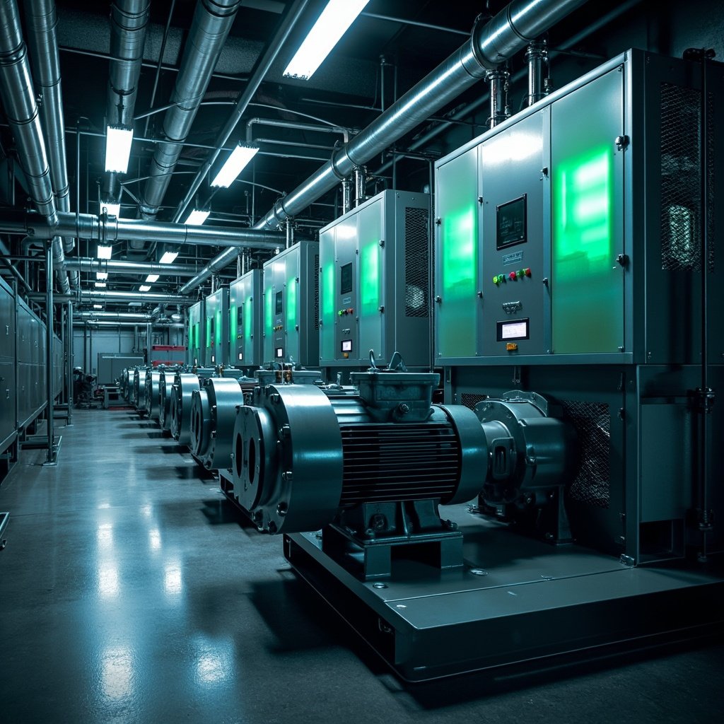
In modern industrial and commercial fluid management systems, VFD multi-pump control has become the gold standard for efficiency, reliability, and energy savings. A Variable Frequency Drive (VFD) regulates the speed of electric motors driving pumps, and when multiple pumps are synchronized through a centralized controller, the system achieves unmatched performance across water treatment plants, HVAC systems, irrigation networks, and industrial process lines. This article explores the technology, working principles, advantages, configurations, and best practices that engineers and facility managers should know to optimize their pumping operations.
What Is VFD Multi-Pump Control?
VFD multi-pump control is an automation strategy that uses one or more variable frequency drives, combined with a master controller (often a PLC or dedicated pump controller), to operate several pumps in parallel. The master controller continuously monitors system variables such as pressure, flow rate, and tank level and adjusts the speed of each pump accordingly. By staging pumps on or off and modulating their speed, the system meets demand precisely while minimizing energy consumption and mechanical wear.
Core Concept of Variable Frequency Drives
A VFD controls motor speed by varying the frequency and voltage supplied to the AC motor. The relationship between motor speed (N), frequency (f), and number of poles (P) follows the formula: N = 120 × f / P. By lowering the frequency, the drive reduces pump speed, which in turn reduces flow and pressure. Affinity laws govern this relationship:
- Flow is directly proportional to speed: Q₂ / Q₁ = N₂ / N₁
- Pressure (head) varies with the square of speed: H₂ / H₁ = (N₂ / N₁)²
- Power consumption varies with the cube of speed: P₂ / P₁ = (N₂ / N₁)³
The cubic relationship between power and speed means that even small reductions in pump speed yield massive energy savings—often 30% to 60% in variable-demand systems.
How VFD Multi-Pump Systems Work
The master controller uses a feedback loop to maintain a target setpoint—usually a process pressure or flow value. Sensors transmit real-time data to the controller, which compares the measured value to the setpoint. If demand rises, additional pumps are brought online and ramped up; if demand falls, pumps are ramped down or switched off entirely. This process is called pump staging or cascade control.
Common Control Modes
- Lead-Lag Control: A primary (lead) pump runs continuously, with lag pumps activated as demand increases. Roles rotate to equalize wear.
- Parallel Cascade: All running pumps operate at similar speeds, increasing total capacity proportionally.
- Jockey Pump Mode: A small pump handles low-demand periods while main pumps engage only at peak load.
- Sensorless Control: Advanced drives estimate flow/pressure without external sensors using motor feedback.
Key Components of a Multi-Pump VFD System
A robust multi-pump installation combines hardware and software elements working in concert. The table below summarizes the essential components.
| Component | Function | Typical Specification |
|---|---|---|
| VFD | Modulates motor frequency and voltage | 1 HP – 500 HP, 380–480V |
| Pump Motors | Drive centrifugal or positive displacement pumps | TEFC, IE3/IE4 efficiency |
| Master Controller (PLC) | Coordinates staging and setpoint logic | Allen-Bradley, Siemens, Schneider |
| Pressure Transducer | Provides real-time process feedback | 4–20 mA, 0–10 bar range |
| Flow Meter | Measures system throughput | Electromagnetic or ultrasonic |
| HMI/SCADA | Operator interface and data logging | 10–15″ touchscreen, Ethernet |
Major Benefits of VFD Multi-Pump Control
Implementing VFD multi-pump control delivers quantifiable benefits across operational, financial, and environmental dimensions.
- Energy Efficiency: Motors running at 60–80% speed consume dramatically less power, translating to 30–60% utility savings.
- Reduced Mechanical Stress: Soft starts and stops minimize water hammer, impeller wear, and bearing fatigue.
- Improved Process Control: Tight pressure or flow regulation prevents surges and improves product quality.
- Extended Equipment Life: Equalized run-time across pumps ensures no single unit is overworked.
- Lower Maintenance Costs: Predictive diagnostics and fault logging reduce unplanned downtime.
- Remote Monitoring: SCADA integration enables real-time visibility from anywhere via cloud platforms.
⚠️ Pro Tip: Always size your VFD for at least 125% of the motor’s full-load current. Underrated drives cause nuisance tripping and premature failure, especially during simultaneous pump staging events where inrush currents can spike.
Common Applications
VFD multi-pump control is deployed across a wide spectrum of industries, including:
- Municipal Water Supply: Maintaining constant line pressure in distribution networks.
- HVAC Systems: Variable chilled water and condenser water pumping in commercial buildings.
- Irrigation: Center-pivot and drip systems with fluctuating demand zones.
- Wastewater Treatment: Lift stations and aeration basins with varying loads.
- Oil & Gas: Crude transfer, injection pumps, and pipeline boosters.
- Industrial Process Cooling: Maintaining stable temperatures in chemical and pharmaceutical plants.
Design Best Practices
A well-engineered VFD multi-pump system accounts for both electrical and hydraulic factors. Follow these best practices for optimal results:
- Use Individual Drives Per Pump: Avoid one large drive running multiple pumps; independent control offers redundancy and flexibility.
- Implement Bypass Circuits: Each VFD should have a bypass contactor to allow line-start operation during drive failure.
- Set Proper Acceleration/Deceleration Ramps: Typical values are 5–15 seconds to prevent hydraulic transients.
- Install Output Reactors or dV/dt Filters: Protect motor windings from reflected voltage waves on long cable runs.
- Enable Sleep Mode: Drives should ramp down and enter standby when demand falls below a threshold for extended periods.
- Configure Alternation Logic: Ensure pumps share run hours equally, not just by sequential starting.
VFD vs. Conventional Multi-Pump Control
The performance gap between traditional on/off staging and VFD-based systems is substantial. The table below compares both approaches.
| Parameter | Conventional Control | VFD Multi-Pump Control |
|---|---|---|
| Energy Use | Fixed, high consumption | Proportional to demand (up to 60% savings) |
| Pressure Stability
|