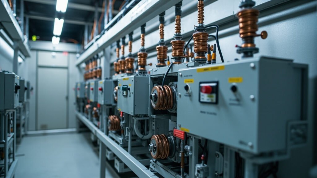
SINAMICS Line Supply and DC-Link Architecture: Active Line Module 6SL3330-6TE41-3AA3, Diode Rectifier C74103-A1900-A351, and 6SL3000 Line Reactor Duty


SINAMICS Line Supply and DC-Link Architecture: Active Line Module 6SL3330-6TE41-3AA3, Diode Rectifier C74103-A1900-A351, and 6SL3000 Line Reactor Duty
Industrial drive cabinets combine two distinct power paths: the line side converts mains power into a controlled DC bus, while the motor side draws from that bus to operate the machine. Selecting those paths independently is essential because a suitable motor power unit does not automatically include the rectifier, line impedance, regenerative capability, and protective measures required by its installation. The correct design also depends on whether axes share a DC bus, how much regenerative energy must be returned, and whether the supply can tolerate the resulting current harmonics.
This article examines the architecture around three key components: an active line module, a diode rectifier module, and a line reactor. Their roles are complementary rather than interchangeable. It also explains why a listing voltage must be checked against the actual supply, why a reactor must be sized for aggregate cabinet current, and why used equipment requires careful identification before installation.
The Line Side Is a Separate Design Decision
The line side must be designed for the available mains supply, the required DC-link voltage, the expected regenerative duty, and the cabinet’s harmonic environment. It should not be treated as an automatic accessory of the motor power unit. Our listing for the Siemens 6SL3330 Active Line Module identifies the 6SL3330-6TE41-3AA3-Z as an Active Line Module for 380-480 V AC with 150 kW rated power, 50/60 Hz operation, 98 percent efficiency, IP20 protection, forced-air cooling, and an ambient range of -10 to +50 C.
An Active Line Module uses controlled switching rather than simple uncontrolled rectification. Its internal regulation and filtered input inductance help establish a controlled DC-link voltage, while the active path can return energy to the mains when regenerative operation is permitted. “Active” does not mean that harmonics disappear. Input current remains shaped by the switching process, the line impedance, the supply, and the filter arrangement.
Several listings also show that control voltage is a separate design item. The 6SL3121-1TE21-8AA4, for example, is listed with 24 V DC control supply even though its main input is three-phase AC. A suitable control transformer or supply module must therefore be included in the cabinet design. Likewise, the 6SE7090-0XX84-0KA0 is listed as a plug-in PROFIBUS DP communication board with 12 Mbps communication, 24 V DC, and compatibility with SINAMICS drives. It is an option for the appropriate control-unit generation, not a guarantee that every drive includes communications.
For used or spare parts, request the operating history and inspect the unit for capacitor or fan condition. Confirm that a Z suffix or other option code in the order number is identical before treating two assemblies as interchangeable.
Diode, Thyristor and Active Front Ends Compared
A diode rectifier is normally the simplest and least expensive front end. It provides uncontrolled conversion from three-phase AC to DC and requires no switching command for basic rectification. Its disadvantages are equally clear: line current contains significant harmonics, the DC-link voltage is not actively regulated, and energy cannot be returned through the diode path to the mains.
Our listing for the Siemens C74103-A1900-A351 diode rectifier module describes the C74103-A1900-A351 as a three-phase full-wave diode rectifier for compatible SINAMICS G120 power units. The listing states 380-480 V AC three-phase input at 47-63 Hz, 16 A nominal current at 400 V AC, and an approximately 540-650 V DC-link output. It associates the module with the 7.5 kW power-unit class and names the 6SL3210-5FE10-4UA0 as compatible.
A thyristor line-commutated feed uses phase-angle control and can provide inherent regeneration on AC-fed DC drives such as the listed SIEMENS 6RA8018-6DV62-0AA0. That controller is rated at 55 A armature current and 22 kW from a 400 V three-phase supply, with a 10-1000 V DC armature range. Regeneration capability does not eliminate the trade-offs: displacement factor and line harmonics depend on firing angle and load conditions.
The active front end occupies the third category. It adds controlled switching and regulation, supports regenerative feed back to the mains within the equipment’s limits, and can reduce the disadvantages associated with passive rectification. These benefits must still be balanced against cost, cabinet requirements, filtering, thermal load, and supply compatibility.
DC-Link Voltage and What Sets the Band
The DC-link voltage follows from the AC line voltage and the rectification method. For a balanced three-phase supply expressed as line-to-line RMS voltage, the approximate peak line-to-line voltage is:
V_{\text{peak}} \approx \sqrt{2} \times V_{\text{LL}}
\]
with volts in both terms. At 400 V AC, the worked multiplication is 400 V x 1.414, giving approximately 566 V. Applying the same relationship to 480 V AC gives approximately 679 V. The approximately 540-650 V DC range attributed to the C74103-A1900-A351 listing is therefore describing a rectified peak band associated with the stated 380-480 V AC input, rather than an arbitrary DC value.
This arithmetic is a design check, not a substitute for the manufacturer data sheet. Actual bus behavior, switching margin, control settings, and permissible operating states must be confirmed for the exact drive configuration. The connected motor power unit must also support the voltage established by the chosen front end.
A common-DC-bus cabinet creates a particularly important restriction: the DC bus must never be exposed to a voltage above the range supported by its power units. A higher supply class may produce a higher rectified voltage and can damage every power unit connected to that bus. Mixed supply classes should not be combined merely because their nominal AC ratings appear close.
The practical selection sequence is therefore straightforward. Confirm the incoming supply, calculate the expected rectified voltage, compare it with the permitted DC-link range, and then verify that the chosen line module or rectifier belongs to the intended drive architecture. If regenerative equipment will later be added, its bus voltage and commutation requirements must also be included in that comparison.
Common DC Bus or One Rectifier per Drive
A shared DC bus allows one line module to feed several booksize or chassis power units. This arrangement avoids repeated rectification, reduces the number of front-end assemblies, and allows axes on the same bus to share braking energy. It is attractive when several drives must start, stop, and exchange energy in a coordinated sequence.
The trade-off is electrical and operational coupling. A fault affecting the common bus, its line module, or a protective device can affect every connected axis. Cable routing and fault isolation also require careful planning. Separate rectifiers retain more independent fault domains and may simplify installation in machines where the axes do not benefit from shared energy.
The 6SL3121-1TE21-8AA4 represents another architectural choice. Our listing describes it as a SINAMICS S120 Combi single-axis unit combining an integrated line module and motor power module. It is listed at 30 kW, with three-phase 380-480 V AC input at 47-63 Hz, 24 V DC control supply, forced-air cooling, and a weight of about 28 kg. Combining the line and motor electronics reduces cabinet space and the number of separately commissioned parts, but it gives up some of the flexibility offered by a shared bus or separately selected rectifier.
For comparison, the 6SL3352-1AE33-8AA1 power unit is listed for 400-480 V AC three-phase input at 15 kW, with 32 A output current, 96 percent efficiency, IP54 protection, forced air, and 45 kg weight. The 6SL3330-6TE41-7AA3-ZT93 is listed as a SINAMICS S120 Feedback Rectifier Unit for designs requiring an active return path.
Line Reactors, Harmonics and the Point of Common Coupling
A line reactor adds impedance between the supply and the drive, helping reduce harmonics and protect equipment against voltage spikes. Our listing for the Siemens 6SL3000-0CH36-0AA0 line reactor specifies 400 V AC, 1.5 mH inductance, 30 A current rating, 50/60 Hz operation, insulation class F, panel mounting, and an ambient range of -25 to +60 C. It also describes harmonic reduction and protection against voltage spikes.
Its current rating must cover the aggregate RMS line current of the connected load, not merely one drive. The inductance and voltage class must also be suitable for the actual installation. For a single line reactor, the reactive reactance is:
X_L = 2 \times \pi \times f \times L
\]
where \(X_L\) is in ohms, \(f\) is in hertz, and \(L\) is in henries. At 50 Hz, the indicative calculation is 2 x 3.1416 x 50 x 0.0015 H, giving approximately 0.47 ohm. At the listed 30 A rating, this corresponds to roughly 14 V of reactive drop before winding resistance is counted. Real voltage drop, loss, and thermal performance must come from the manufacturer data.
Before ordering or applying one, confirm these points:
- The total RMS line current remains within the reactor’s 30 A rating.
- The supply voltage and frequency remain within the listed operating class.
- The cabinet can dissipate the reactor’s losses and maintain its specified ambient conditions.
- The installation’s point of common coupling and utility agreement determine whether additional filtering is required.
Harmonic limits at the point of common coupling are governed by the utility agreement and IEEE 519 practice rather than solely by the drive manual. See our existing guide to VFD harmonic mitigation reactors and filters for the filter-versus-reactor decision without repeating the broader mitigation discussion.
Regenerative Braking Without a Resistor Bank
A diode-fed drive cannot return energy through its uncontrolled rectifier. During deceleration or overhauling loads, the DC-link voltage can rise. A braking chopper then connects a resistor bank to dissipate that energy as heat. The required resistor resistance, power rating, duty cycle, and thermal derating are covered in our VFD braking resistor selection article.
An active or feedback rectifier changes the destination of that energy. Instead of relying primarily on resistor dissipation, it feeds energy back into the mains within the permitted DC-link limits. The 6SL3330-6TE41-3AA3-Z listing presents the Active Line Module as regenerative, while the 6SL3330-6TE41-7AA3-ZT93 is identified as a Feedback Rectifier Unit.
Regeneration is not automatically preferable in every installation. It can require additional line-side provisions, compatible supply arrangements, and careful protection coordination. It can also affect the voltage seen by other equipment on the same supply. The deciding factors are the deceleration duty cycle, how often the axis reverses or regenerates, the available bus voltage margin, and whether the upstream system can accept returned energy.
With a diode feed, those same factors determine the braking-chopper and resistor requirements. With an active front end, resistor capacity may still be needed for exceptional or non-regenerative operating conditions. The architecture should therefore be selected from the machine’s energy profile rather than from the rectifier category alone.
| Component | What our listing states | What it does in the architecture | What you must still confirm |
|---|---|---|---|
| 6SL3330-6TE41-3AA3-Z | Active Line Module; 380-480 V AC; 150 kW; 50/60 Hz; 98 percent efficiency; IP20; -10 to +50 C; forced air | Actively converts the line supply and supports regenerative feed back to the mains | Exact compatibility, control configuration, cooling, and permitted bus conditions |
| C74103-A1900-A351 | Three-phase full-wave diode rectifier; 380-480 V AC at 47-63 Hz; 16 A nominal at 400 V AC; approximately 540-650 V DC output | Provides uncontrolled rectification for compatible SINAMICS G120 power units | Drive compatibility, thermal margin, bus voltage, and whether a braking chopper is required |
| 6SL3000-0CH36-0AA0 | Reactor; 1.5 mH; 30 A; 400 V AC; 50/60 Hz; insulation class F; -25 to +60 C | Adds line impedance to reduce harmonics and protect against voltage spikes | Aggregate load current, source conditions, losses, point-of-common-coupling requirements |
| 6SL3121-1TE21-8AA4 | SINAMICS S120 Combi single-axis unit; integrated line and motor modules; 30 kW; 380-480 V AC at 47-63 Hz; 24 V DC control supply | Combines line conversion and motor electronics in one package | Exact power-unit class, motor data, regenerative mode, control supply, and cabinet thermal design |
Frequently Asked Questions
Can the 6SL3330-6TE41-3AA3-Z replace the C74103-A1900-A351?
Not directly. They belong to different front-end approaches: one is listed as an active line module, while the other is an uncontrolled diode rectifier. Compatibility depends on the complete SINAMICS system, power class, control configuration, bus requirements, and regenerative strategy.
Does a 480 V AC supply automatically mean a 480 V DC bus?
No. The DC-link voltage depends on the rectification topology and operating conditions. The article gives the approximate peak relationship for the stated three-phase AC inputs, but the manufacturer data sheet must establish the permissible bus range for the selected equipment.
Can one line reactor serve several drives?
Possibly, but its rating must cover their aggregate RMS line current and installation conditions. The listed 30 A rating cannot be allocated independently to each connected drive. Harmonic behavior at the common connection must also be assessed against the utility agreement.
Are used SINAMICS modules interchangeable with new units?
Only after their exact order codes, option identifiers, revisions, and operating histories have been checked. Capacitors and fans should be inspected, and all electrical ratings must match the intended application. A visually similar unit is not sufficient evidence of interchangeability.
What determines the need for a braking resistor?
The machine’s deceleration duty cycle and the drive’s ability to return energy are central. A diode feed normally requires a chopper and resistor for regenerative energy, whereas an active or feedback rectifier can return it to the mains within its limits. The worst-case bus rise still has to be checked.
The most reliable drive design starts with the incoming supply, motor data, and energy profile, then selects the rectifier architecture before finalizing the DC bus and protective equipment. Line reactors, control supplies, communications, cooling, and braking provisions must then be matched to the complete cabinet rather than ordered as isolated parts.
Our team can cross-reference the exact part number, stated configuration, and current lead time against your application, helping identify the correct replacement before an order is placed.