

VFD Harmonic Mitigation: Reactors, Filters and IEEE 519

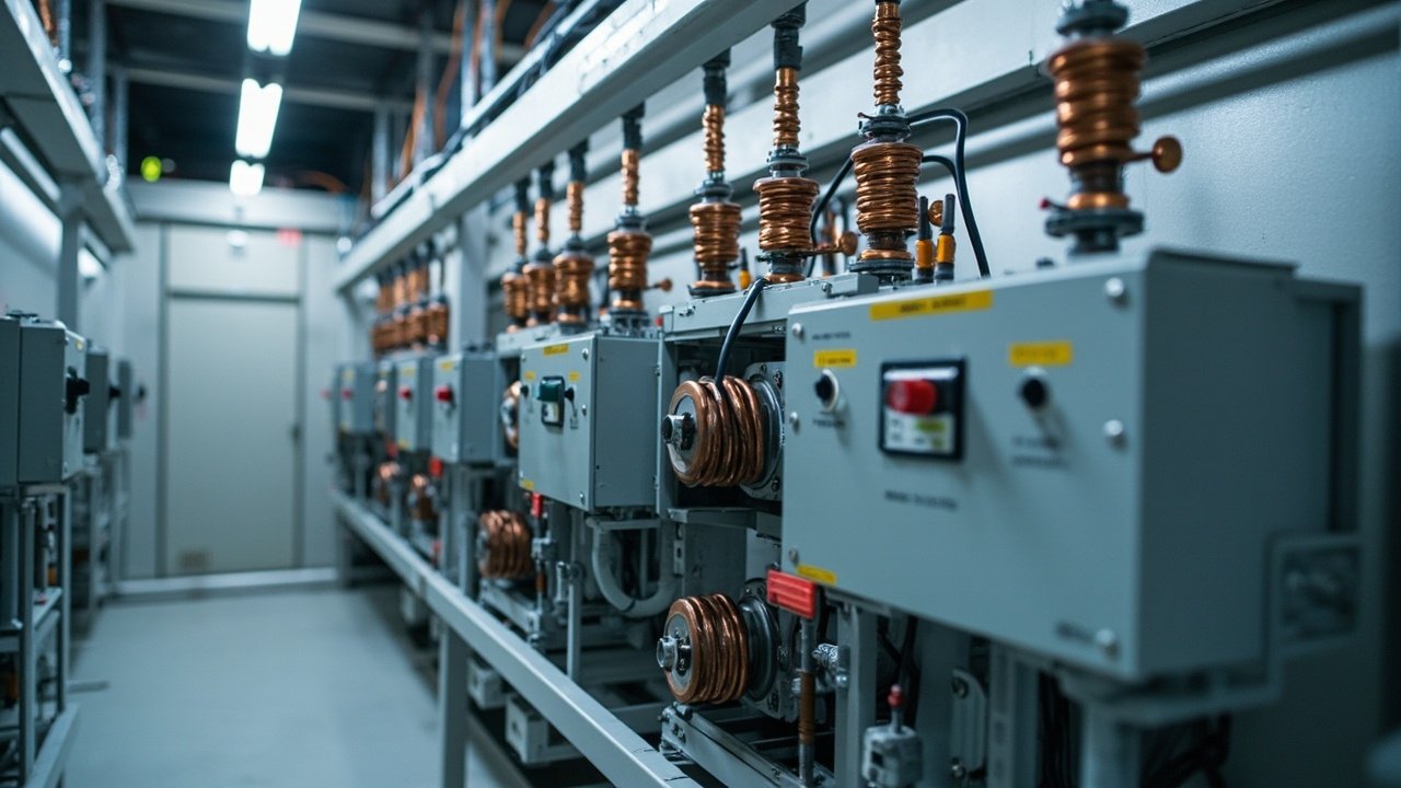
Choosing the right VFD harmonic mitigation strategy is crucial for preventing equipment damage, avoiding operational disruptions, and meeting IEEE 519 compliance. This article guides you through calculating harmonics, understanding their effects, and selecting the optimal mitigation solution for your application.
Understanding Drive Harmonics and Their Impact
Variable frequency drives (VFDs) are widely used for motor speed control but generate harmonics that distort the current waveform. These harmonics, primarily odd multiples of the fundamental frequency (e.g., 3rd, 5th, 7th), flow through the power system and cause several issues:
- Neutral Overheating: Triplen harmonics (3rd, 9th, etc.) add in the neutral conductor, causing it to overheat and potentially fail.
- Capacitor Failure: Harmonic currents increase capacitor RMS current, leading to overheating and premature failure.
- Nuisance Trips: High harmonic distortion can cause protective devices to trip, disrupting operations.
- Transformer Overheating: Harmonics increase eddy current and hysteresis losses, leading to overheating and reduced transformer life.
The cost of ignoring harmonics includes frequent equipment replacement, unplanned downtime, and increased energy consumption. The mechanism is measurable rather than theoretical: harmonic currents add I²R loss in conductors and transformer windings, and the triplen components add in the neutral rather than cancelling. Understanding these effects is crucial for designing reliable and efficient electrical systems.
Calculating Harmonic Distortion and IEEE 519 Compliance
Harmonic distortion is quantified using Total Harmonic Distortion (THD) and Total Demand Distortion (TDD). The formulas are:
THD = (√(Σ I_h²)) / (I_1) × 100%
TDD = (√(Σ I_h²)) / (I_L) × 100%
Where:
- I_h = RMS current at harmonic order h
- I_1 = RMS fundamental current
- I_L = Maximum demand load current at fundamental frequency
Worked Example
Consider a VFD with the following harmonic currents:
- Fundamental current (I_1) = 100 A
- 5th harmonic current (I_5) = 20 A
- 7th harmonic current (I_7) = 14 A
- 11th harmonic current (I_11) = 10 A
First, calculate the sum of the squares of the harmonic currents: Σ I_h² = 20² + 14² + 10² = 400 + 196 + 100 = 696
Next, calculate THD: THD = (√(696)) / (100) × 100% = 26.4%
Assuming the maximum demand load current (I_L) is 150 A, calculate TDD: TDD = (√(696)) / (150) × 100% = 17.6%
That figure is above the current limits in IEEE 519 for any Isc/IL band, so some form of mitigation is required rather than optional.
IEEE 519 Compliance
IEEE 519 does not publish one fixed current limit. The permitted harmonic current at the point of common coupling is scaled by the stiffness of the supply, expressed as the ratio of available short-circuit current to maximum load current (Isc/IL). A weak supply tolerates a larger distortion; as the ratio grows the individual harmonic limits and the total demand distortion limit tighten. Voltage distortion at the same point is capped separately, and the cap is set by the system voltage class, so read the table for your voltage level and Isc/IL band in the current edition of the standard and confirm the number your utility applies.
Selecting the Right Harmonic Mitigation Solution
Choosing the appropriate mitigation technique depends on several factors, including the level of harmonic distortion, cost, space constraints, and specific application requirements. The following table compares the key characteristics of different mitigation methods:
| Mitigation option | What it actually changes | Cost and space | Where it is the right answer |
|---|---|---|---|
| AC line reactor | Adds source impedance, smooths the DC-link charging spikes and protects the drive front end | Low cost, small copper and core loss | First option on a weak transformer or a single drive |
| DC link reactor | Same current-shaping effect, fitted inside the DC circuit | Low cost, needs room in the drive | Drives without a spare AC side slot |
| dV/dt filter | Limits the rate of rise of voltage, protecting motor insulation on long cable runs | Medium cost, cabinet space | Motor more than about 50-100 m from the drive |
| Passive filter bank | Detunes one characteristic harmonic order, typically the 5th or 7th | Higher cost, large footprint | Known single-frequency problem on a stiff bus |
| Active front end or active filter | Injects cancelling current across a wide order range and can regenerate | Highest cost, panel space | Multi-drive plants, strict utility agreement, regeneration needed |
Mitigation Selection Criteria
- Cost: Line reactors are the most cost-effective solution, while active filters are the most expensive.
- Space: Passive filter banks require more space due to their larger size.
- Performance: Active filters offer the highest harmonic reduction but at a higher cost and complexity.
- Maintenance: Line reactors and dV/dt filters require minimal maintenance, while passive and active filters may need more frequent servicing.
Installing the Mitigation Hardware
Step-by-Step Procedure
- Site Preparation: Ensure the installation area is clean, well-ventilated, and free from moisture.
- Mounting: Mount the mitigation device according to the manufacturer’s guidelines. Ensure proper clearance for heat dissipation.
- Wiring:
- Connect the input and output terminals according to the wiring diagram.
- Use appropriately sized cables to handle the harmonic currents.
- Ensure all connections are tight and secure.
- Grounding: Connect the device’s ground terminal to the main grounding system to prevent electrical noise and ensure safety.
- Commissioning:
- Power up the system and check for any abnormal noises or vibrations.
- Measure the harmonic distortion levels using a power quality analyzer to verify the mitigation performance.
- Adjust the settings if necessary to achieve optimal performance.
Diagnosing Harmonic Problems in Service
Symptoms and What They Indicate
- Overheating: Equipment such as transformers, capacitors, and conductors may overheat due to increased losses.
- Nuisance Tripping: Protective devices may trip due to harmonic-induced current fluctuations.
- Voltage Distortion: High voltage distortion can cause erratic equipment behavior and reduced efficiency.
Diagnosis
- Measurement: Use a power quality analyzer to measure harmonic levels at the point of common coupling.
- Analysis: Compare the measured values with IEEE 519 limits to determine if mitigation is required.
- Root Cause Analysis: Identify the source of harmonics, which is often VFDs or other non-linear loads.
Troubleshooting
- Overheating: Check for loose connections, inadequate cooling, or undersized conductors.
- Nuisance Tripping: Verify the settings of protective devices and consider adjusting them to accommodate harmonic currents.
- Voltage Distortion: Implement harmonic mitigation techniques such as line reactors or active filters to reduce distortion.
Measuring, Documenting and Defending a Compliance File
Accurate measurement of harmonic distortion is crucial for demonstrating IEEE 519 compliance and ensuring the effectiveness of your mitigation strategy. The process begins with selecting appropriate measurement points in the power system. Typically, measurements are taken at the point of common coupling (PCC), which is the point where the utility service meets the customer load. This location is critical because it represents the point at which the utility imposes limits on harmonic distortion.
To measure harmonic distortion, use a power quality analyzer that complies with IEC 61000-4-7 standards. These devices can capture harmonic data up to the 50th order, which is essential for comprehensive analysis. The measurement should be conducted under normal operating conditions to ensure that the data reflects real-world usage. Record the total harmonic distortion (THD) for both voltage and current, as well as the individual harmonic orders up to the 25th, which are typically the most significant contributors to distortion.
Documentation of the measurement process and results is vital for defending your compliance file. Create a detailed report that includes:
- Date, time, and duration of the measurement
- Equipment used, including make, model, and calibration status
- Measurement points and conditions
- Tabulated data of THD and individual harmonic orders
- Comparison with IEEE 519 limits
This report should be accompanied by a narrative that explains the methodology and justifies any deviations from ideal conditions. For instance, if measurements were taken during a period of unusually high demand, this should be noted and its impact on the results discussed.
Defending your compliance file may also involve providing evidence of the effectiveness of your chosen mitigation strategy. This can be achieved by comparing pre- and post-mitigation measurements. If the harmonic levels are significantly reduced and meet IEEE 519 requirements, this strengthens your case for compliance. Additionally, maintaining a log of any changes to the power system or mitigation equipment can help demonstrate ongoing compliance.
Thermal and Neutral Consequences Already Hiding in the Panel
When implementing harmonic mitigation solutions, it’s important to consider the thermal implications within the electrical panel. Harmonic currents, particularly those of higher frequencies, can cause additional heating in conductors and transformers due to the skin effect and increased eddy current losses. This can lead to premature aging of components and, in severe cases, failure of the equipment.
The skin effect causes high-frequency currents to flow predominantly on the surface of conductors, reducing the effective cross-sectional area and increasing resistance. This effect is more pronounced in larger conductors and at higher frequencies. To mitigate this, consider using multiple smaller conductors in parallel, which can help distribute the current more evenly and reduce heating.
Neutral conductors are particularly susceptible to overheating due to the presence of triplen harmonics (3rd, 9th, 15th, etc.), which are additive in the neutral. In a three-phase system, these harmonics can cause the neutral current to exceed the phase current, leading to overheating and potential fire hazards. To address this, ensure that the neutral conductor is oversized and that the panel is designed to accommodate the additional heat load.
Thermal management strategies may include:
- Increasing the cross-sectional area of conductors
- Using conductors with a higher temperature rating
- Installing additional cooling, such as fans or heat exchangers
- Implementing derating factors for transformers and other components
When selecting mitigation equipment, consider the thermal characteristics of the panel and the additional heat generated by the equipment itself. Active filters, for example, can introduce heat into the panel, while passive filters may require additional space for heat dissipation. Balancing the need for harmonic mitigation with thermal management is essential for maintaining the reliability and longevity of the electrical system.
In summary, addressing the thermal and neutral consequences of harmonic distortion requires a comprehensive approach that considers both the immediate and long-term impacts on the electrical panel. By understanding these implications and implementing appropriate mitigation strategies, you can ensure the safe and efficient operation of your power system.
Quick Selection Checklist
- Verify the harmonic current levels and calculate THD and TDD.
- Confirm compliance with IEEE 519 standards.
- Evaluate the cost, space, and performance requirements.
- Consider the maintenance implications of each mitigation method.
- Assess the available space for the mitigation device.
- Check the compatibility with existing equipment and systems.
- Ensure the mitigation device can handle the full range of operating conditions.
- Verify the installation and wiring requirements.
- Confirm the availability of technical support and spare parts.
- Consider the long-term scalability of the chosen solution.
FAQ
How do VFDs generate harmonics?
VFDs generate harmonics due to the non-linear switching action of the inverter. The rapid switching of the IGBTs creates current pulses that distort the current waveform.
What are the IEEE 519 limits for harmonic distortion?
IEEE 519 sets separate caps for voltage distortion at the point of common coupling, and the current limits tighten as the supply becomes stiffer relative to the load.
How do I choose the right harmonic mitigation solution?
Consider factors such as the level of harmonic distortion, cost, space constraints, and specific application requirements. Refer to the comparison table for guidance.
What are the maintenance requirements for different mitigation methods?
Line reactors and dV/dt filters require minimal maintenance, while passive and active filters may need more frequent servicing. Regular inspection and testing are recommended for all mitigation devices.
Specifying the Mitigation Hardware
Ai Electrical supplies line reactors, dV/dt and sine filters, harmonic filters and drive packages for motor control centres. Send the drive rating, supply voltage and short-circuit current at the point of common coupling, and we will size the mitigation hardware before quoting.
Related Reactors and Filters
- Allen-Bradley 1321-3R4-A line reactor
- Siemens 6SL3351-6GE33-8AB3 line filter
- Yaskawa CIPR-GA50B4004ABB inverter drive