

Industrial Temperature Sensor Installation: Thermowell Immersion Depth, Calibration Offset, 4-20mA Transmitter Wiring

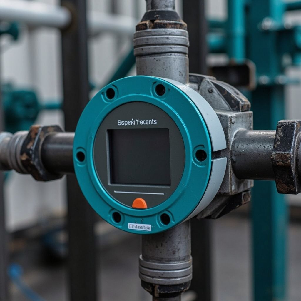
Industrial Temperature Sensor Installation: Thermowell Immersion Depth, Calibration Offset, 4-20mA Transmitter Wiring
Temperature sensors are crucial components in industrial automation, providing essential data for process control, safety, and efficiency. Proper installation of these sensors is vital to ensure accurate and reliable measurements. This article will delve into the critical aspects of industrial temperature sensor installation, including thermowell selection, immersion depth, calibration offset, wiring of 4-20mA transmitters, and common installation errors. We will also reference specific products such as the MESSKO MT-ST160SK/TT Oil Temperature Indicator, MESSKO ZT-F2.1 Temperature Sensor Transmitter, and Omron ES2-THB-N Temperature Sensor.
Thermowell Selection and Immersion Depth
Material Considerations
The choice of thermowell material is critical for ensuring the longevity and accuracy of temperature measurements, especially in harsh environments. Common materials include 316 Stainless Steel (316SS) and Hastelloy.
| Material | Corrosion Resistance | Temperature Range | Cost |
|---|---|---|---|
| 316SS | Good | -254°C to 816°C | Low |
| Hastelloy | Excellent | -200°C to 1093°C | High |
- 316SS: Offers good corrosion resistance and is suitable for most industrial applications. It is cost-effective and widely used in environments where corrosion is a concern but not extreme.
- Hastelloy: Provides excellent corrosion resistance and is ideal for highly corrosive environments, such as those involving acids or seawater. It is more expensive but offers superior durability.
Immersion Depth
The immersion depth of a thermowell is crucial for accurate temperature measurement. A common rule of thumb is that the immersion depth should be at least 10 times the stem diameter of the thermowell. Alternatively, for pipes, the immersion depth should extend to the centerline of the pipe.
- Minimum Immersion Depth: 10 times the stem diameter ensures that the sensor is not affected by external heat sources and provides a representative temperature reading.
- Pipe Centerline: Extending the thermowell to the centerline of the pipe ensures that the sensor measures the bulk temperature of the fluid, rather than the temperature of the pipe wall.
Example
For a thermowell with a stem diameter of 1 inch, the minimum immersion depth would be 10 inches. This ensures that the sensor is sufficiently immersed to provide accurate readings.
RTD and Thermocouple Configuration
RTD Pt100 Configuration
RTDs (Resistance Temperature Detectors) are popular for their high accuracy and stability. The Pt100 configuration is common in industrial applications.
| Configuration | Wires | Accuracy | Cost |
|---|---|---|---|
| 2-wire | 2 | Low | Low |
| 3-wire | 3 | Medium | Medium |
| 4-wire | 4 | High | High |
- 2-wire: Simple and cost-effective but susceptible to lead resistance errors.
- 3-wire: Compensates for lead resistance and offers a good balance between accuracy and cost.
- 4-wire: Provides the highest accuracy by eliminating lead resistance but is more complex and expensive.
Thermocouple Type Selection
Thermocouples are versatile and can measure a wide range of temperatures. The choice of thermocouple type depends on the temperature range and the environment.
| Type | Temperature Range | Environment | Cost |
|---|---|---|---|
| J | -210°C to 1200°C | General | Low |
| K | -270°C to 1372°C | General | Low |
| T | -270°C to 400°C | Cryogenic | Medium |
| E | -270°C to 1000°C | General | Medium |
| N | -270°C to 1300°C | General | Medium |
| S | -50°C to 1768°C | High Temp | High |
| R | -50°C to 1768°C | High Temp | High |
| B | 0°C to 1820°C | High Temp | High |
- Type J: Suitable for general-purpose applications and is cost-effective.
- Type K: Offers a wide temperature range and is commonly used in general industrial applications.
- Type T: Ideal for cryogenic applications due to its low-temperature capabilities.
- Type E: Provides good accuracy and is suitable for general applications.
- Type N: Offers a wide temperature range and is more stable than Type K at high temperatures.
- Types S, R, B: Used for high-temperature applications and are more expensive.
4-20mA Transmitter Wiring and Power Supply
Wiring
The 4-20mA current loop is a standard in industrial applications due to its robustness and long-distance capabilities. The wiring of the transmitter is critical to ensure accurate and reliable data transmission.
- Loop Wiring: The transmitter is connected in series with the power supply and the receiver. The current in the loop varies between 4mA and 20mA, representing the measured temperature.
- Shielding: It is essential to use shielded cables to protect against electromagnetic interference.
- Grounding: Proper grounding is necessary to prevent ground loops and ensure the integrity of the signal.
Power Supply Requirements
The power supply for a 4-20mA transmitter must be stable and within the specified voltage range of the transmitter.
- Voltage Range: Typically, 12V to 36V DC is required, depending on the transmitter specifications.
- Current Capacity: The power supply must be able to provide sufficient current for the loop, usually up to 20mA.
Example
For the MESSKO ZT-F2.1 Temperature Sensor Transmitter, the power supply should be between 12V and 36V DC, and the current consumption is typically around 4mA at 4mA output and 20mA at 20mA output.
Calibration Offset Verification
Reference Standards
Calibration is essential to ensure the accuracy of temperature measurements. The calibration offset should be verified against reference standards such as ASTM E1137 and IEC 60751.
- ASTM E1137: Specifies the standard specification for industrial platinum resistance thermometers.
- IEC 60751: Defines the tolerance and accuracy of platinum RTDs.
Verification Process
- Initial Calibration: The sensor is calibrated against a reference standard at known temperatures.
- Offset Calculation: The difference between the measured and actual temperatures is calculated.
- Adjustment: If the offset is outside the acceptable range, the sensor is adjusted to correct the error.
- Re-verification: The sensor is re-tested to ensure that the calibration offset is within the specified tolerance.
Example
For the Omron ES2-THB-N Temperature Sensor, the calibration offset should be verified using a certified reference thermometer and adjusted if necessary.
Common Installation Errors
Insulation Resistance
- Issue: Poor insulation can lead to leakage currents, affecting the accuracy of the temperature measurement.
- Solution: Ensure that the insulation resistance is within the specified range and use high-quality insulating materials.
Thermal Lag
- Issue: A delay in the sensor’s response to temperature changes can lead to inaccurate readings.
- Solution: Use sensors with fast response times and ensure proper thermal contact between the sensor and the medium being measured.
Stem Conduction Error
- Issue: Heat conduction through the thermowell can cause errors in the temperature measurement.
- Solution: Minimize stem conduction by using materials with low thermal conductivity and ensuring proper immersion depth.
Example
In the case of the DYNISCO PT462E High-Temperature Pressure Transmitter, it is crucial to ensure that the stem conduction error is minimized by using a thermowell with low thermal conductivity and maintaining the correct immersion depth.
Digital Communication and Smart Sensors
HART Protocol Configuration for Smart Temperature Transmitters
The Highway Addressable Remote Transducer (HART) protocol is a widely used method for configuring and communicating with smart temperature transmitters. HART allows for two-way digital communication over traditional 4-20mA analog wiring, enabling remote configuration, diagnostics, and calibration. To configure a smart temperature transmitter using HART, a HART communicator or a PC with HART modem software is required. The setup involves connecting the communicator to the transmitter and accessing the device’s configuration menu. Parameters such as sensor type, measurement range, damping, and alarm settings can be easily adjusted. This flexibility simplifies the commissioning process and allows for quick adjustments in the field without the need to physically access the transmitter.
Fieldbus Foundation (FF) Integration
Fieldbus Foundation (FF) is a digital communication protocol that enables more comprehensive integration of smart sensors into a plant’s control system. Unlike HART, which operates over analog lines, FF uses a purely digital network to communicate between field devices and the control system. This integration allows for a more detailed exchange of information, including advanced diagnostics, device status, and process variables. FF integration reduces wiring complexity by enabling multiple devices to communicate on a single network segment, which can lead to cost savings and improved reliability. The digital nature of FF also enhances the accuracy and speed of data transmission, making it ideal for applications requiring real-time process control.
Digital vs Analog Signal Accuracy
Digital communication protocols like HART and FF offer significant advantages over traditional analog 4-20mA signals in terms of accuracy. Analog signals are susceptible to noise and interference, which can degrade the quality of the transmitted data. In contrast, digital signals are less prone to these issues, providing more reliable and accurate data transmission. Additionally, digital protocols allow for more sophisticated error-checking and correction mechanisms, further enhancing accuracy. This is particularly important in temperature measurement, where precise data is crucial for process control and safety.
Wireless Temperature Monitoring (WirelessHART)
WirelessHART is an extension of the HART protocol that enables wireless communication between field devices and the control system. This technology is particularly beneficial for temperature monitoring in hard-to-reach or hazardous areas where wired connections are impractical. WirelessHART devices can be easily installed and relocated as needed, providing flexibility and reducing installation costs. The wireless nature of these devices also facilitates continuous monitoring and data logging, allowing for better process insight and decision-making.
Diagnostic Capabilities of Smart Sensors vs Conventional 4-20mA Transmitters
Smart sensors equipped with digital communication protocols offer superior diagnostic capabilities compared to conventional 4-20mA transmitters. These smart devices can provide real-time status updates, self-diagnostics, and predictive maintenance alerts. For example, a smart temperature transmitter can detect sensor drift, transmitter failure, or communication errors and alert operators before these issues affect the process. In contrast, conventional transmitters provide limited diagnostic information, often requiring manual inspection to identify problems. The enhanced diagnostic capabilities of smart sensors lead to improved reliability, reduced downtime, and lower maintenance costs.
FAQ
What is the minimum immersion depth for a thermowell?
The minimum immersion depth for a thermowell should be at least 10 times the stem diameter or extend to the centerline of the pipe.
How do I verify the calibration offset of my temperature sensor?
The calibration offset should be verified against a certified reference standard, such as ASTM E1137 or IEC 60751, and adjusted if necessary.
What are the common materials used for thermowells?
Common materials include 316 Stainless Steel (316SS) and Hastelloy, each offering different levels of corrosion resistance and temperature capabilities.
What is the 4-20mA current loop?
The 4-20mA current loop is a standard method for transmitting sensor data over long distances. The current in the loop varies between 4mA and 20mA, representing the measured temperature.
How do I minimize stem conduction error?
Minimize stem conduction by using materials with low thermal conductivity and ensuring proper immersion depth of the thermowell.
Conclusion
Proper installation of industrial temperature sensors is essential for accurate and reliable temperature measurement. This includes selecting the right thermowell material and immersion depth, configuring RTDs and thermocouples correctly, wiring 4-20mA transmitters properly, and verifying calibration offset against reference standards. By avoiding common installation errors, such as insulation resistance issues and stem conduction errors, you can ensure the optimal performance of your temperature sensors.
For reliable temperature monitoring, consider using the MESSKO MT-ST160SK/TT Oil Temperature Indicator, MESSKO ZT-F2.1 Temperature Sensor Transmitter, and Omron ES2-THB-N Temperature Sensor. These products offer robust solutions for various industrial applications, ensuring that your temperature measurements are accurate and dependable.
Call to Action
Explore our wide range of industrial temperature sensors and transmitters to find the perfect solution for your needs. Whether you require a simple temperature indicator or a sophisticated transmitter, we have the products to meet your specifications. Visit our website to browse our selection and place your order today.