

VFD Motor Auto-Tuning: A Complete Step-by-Step Guide for Optimal Performance

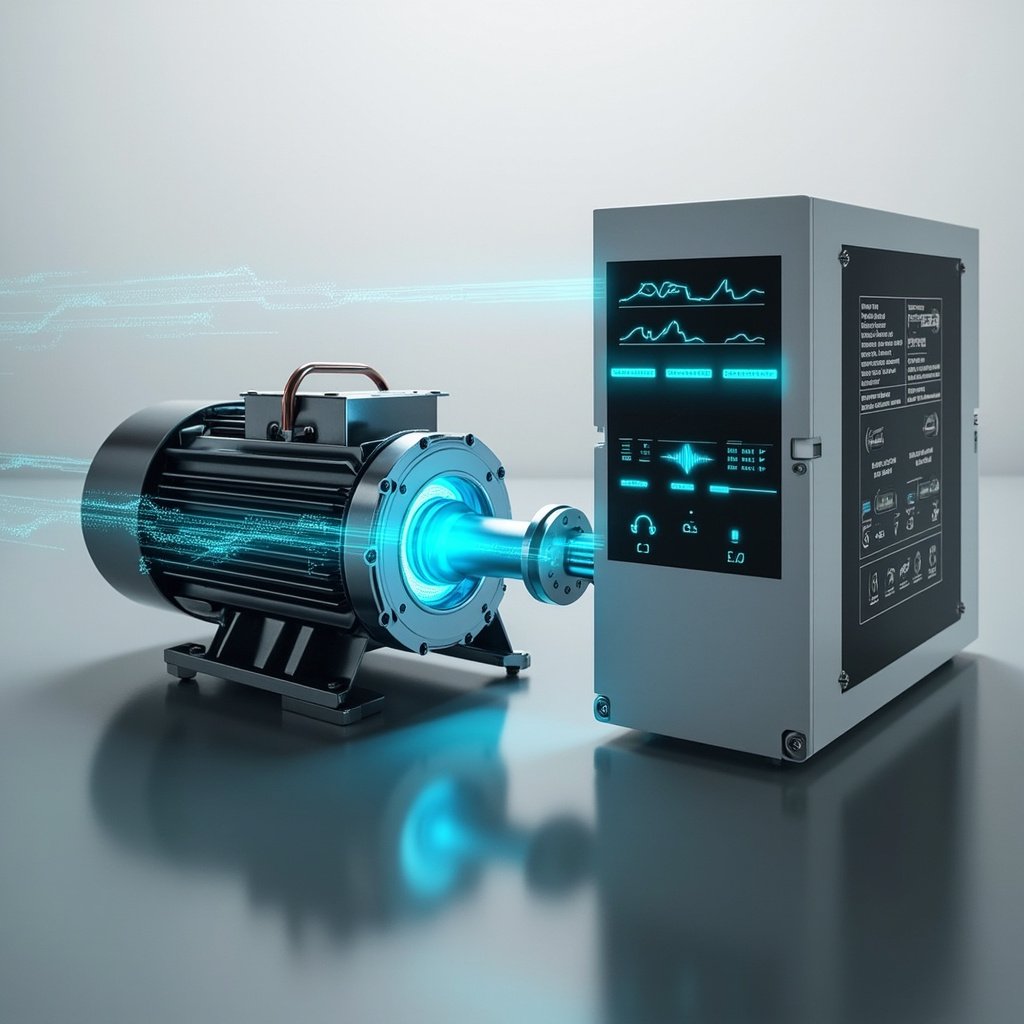
Modern industrial automation relies heavily on Variable Frequency Drives (VFDs) to control the speed, torque, and efficiency of AC induction and permanent magnet motors. One of the most powerful features available in contemporary drives is VFD motor auto-tuning—a built-in commissioning routine that allows the drive to learn the electrical characteristics of a connected motor automatically. Rather than entering complex parameters manually, technicians can run an auto-tune sequence that measures stator resistance, leakage inductance, magnetizing current, and other critical values in minutes, dramatically improving motor performance, energy efficiency, and protection.
This guide explores how VFD motor auto-tuning works, the different tuning methods available, the parameters it measures, common issues you may encounter, and the best practices that ensure long-term reliability.
What Is VFD Motor Auto-Tuning?
VFD motor auto-tuning is a self-calibration procedure in which the drive applies controlled voltage and current signals to a connected motor to identify its nameplate and dynamic electrical parameters. Once measured, these values are stored in the VFD’s memory and used to optimize the motor’s volts-per-Hertz (V/Hz) curve, vector control loops, and torque response. The result is smoother acceleration, lower current draw, reduced heat, and improved speed regulation under varying load conditions.
Why Auto-Tuning Matters
- Performance: Delivers tighter speed and torque control, especially in sensorless vector or closed-loop vector modes.
- Energy Efficiency: Optimizes flux levels, reducing no-load losses and overall kilowatt consumption.
- Motor Protection: Enables accurate thermal modeling and prevents overheating or demagnetization.
- Commissioning Speed: Eliminates guesswork and reduces startup time from hours to minutes.
- Application Flexibility: Allows the same drive to operate a wide variety of motors reliably.
How Auto-Tuning Works
The auto-tune routine injects a series of precisely controlled signals into the motor windings. The VFD measures the resulting current and voltage responses, then uses mathematical models to calculate the motor’s equivalent circuit parameters. The measured values are saved into drive parameters and applied immediately to the active control algorithm.
- Pre-Tune Setup: Enter the motor’s nameplate data—voltage, current, frequency, RPM, and power.
- Decoupling: Mechanically uncouple the motor from the load when required by the selected tuning mode.
- Signal Injection: The VFD applies DC pulses or low-frequency AC to the stator.
- Parameter Calculation: Internal firmware calculates resistance, inductance, slip, and saturation curves.
- Validation: The drive performs a brief test rotation to confirm proper operation before returning to standby.
Types of Auto-Tuning Methods
Different manufacturers and applications require different levels of measurement accuracy. The following table compares the most common auto-tuning methods used in industrial VFDs.
| Tuning Method | Motor Rotation | Accuracy | Typical Use Case |
|---|---|---|---|
| Static (Non-Rotating) | None | Moderate | Coupled loads, conveyor belts, gearboxes |
| Rotational (Spinning) | Yes – uncoupled | High | Pumps, fans, compressors with decoupling |
| Online / Adaptive | Continuous | Very High | High-performance servo and torque applications |
| Manufacturer-Specific (e.g., Yaskawa, ABB, Siemens) | Varies | Optimized per brand | Brand-loyal industrial systems |
Key Parameters Measured During Auto-Tuning
Auto-tuning captures the following electrical and mechanical parameters to build a complete motor model inside the VFD:
- Stator Resistance (Rs): Determines copper losses and influences low-speed torque.
- Leakage Inductance (Lσ): Affects current loop bandwidth and transient response.
- Magnetizing Current (Im): Defines the flux-producing component needed for efficient field orientation.
- Rotor Time Constant (Tr): Critical for accurate slip estimation in indirect field-oriented control.
- Saturation Curve: Models how inductance changes with current, improving torque linearity.
- Encoder Offset (PMSM only): Aligns rotor position feedback in closed-loop vector control.
⚠ Warning: Always ensure the motor is mechanically uncoupled from the load before performing a rotational auto-tune. Failure to do so may result in unexpected motion of connected machinery, potential equipment damage, and serious personal injury. Lock out and tag out (LOTO) all energy sources before beginning the procedure.
Common Issues and Troubleshooting
Even with sophisticated algorithms, auto-tuning can occasionally fail or produce suboptimal results. The most frequent causes include:
- Incorrect nameplate data: A wrong voltage or current entry causes the VFD to miscalculate parameters.
- Excessive cable length: Long motor leads introduce resistance and capacitance errors, particularly above 50 meters.
- Output filter interference: Sine-wave or dV/dt filters can distort measurement signals and require drive-side compensation.
- Motor overheating during tuning: Multiple consecutive tune cycles can heat the windings; allow cool-down between attempts.
- Encoder feedback errors: In closed-loop setups, misaligned or noisy encoders lead to tuning faults.
Best Practices for Reliable Auto-Tuning
- Always verify nameplate data against the motor’s actual rating plate before starting.
- Perform tuning with the motor at ambient temperature for the most accurate resistance readings.
- Use static (non-rotating) tuning when the motor cannot be decoupled from its load.
- Re-run auto-tuning after any significant motor repair, rewinding, or replacement.
- Document and back up parameters after a successful tune for future restoration.
- For PMSM motors, perform a pole-position identification if not already done at the factory.
Auto-Tuning vs. Manual Configuration
While experienced engineers can manually enter motor parameters from test bench data, auto-tuning offers significant advantages for most field installations. Here’s a quick comparison: