

Stepper Motor Stall Detection and Analysis: Causes, Symptoms, and Prevention Methods

Comments Off on Stepper Motor Stall Detection and Analysis: Causes, Symptoms, and Prevention Methods
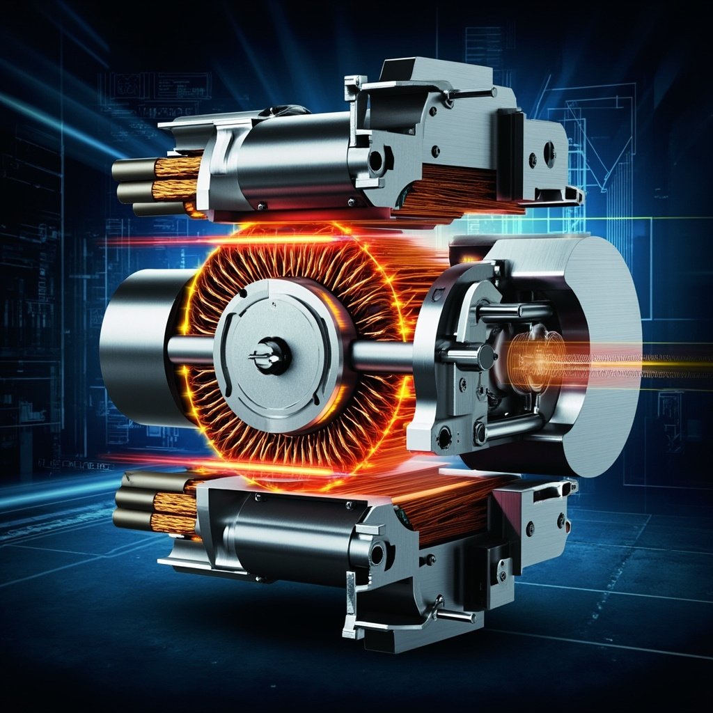
Understanding stepper motor stall analysis is essential for engineers, technicians, and automation professionals who rely on precision motion control systems. A stepper motor stall occurs when the rotor fails to keep up with the commanded step rate, resulting in a complete loss of synchronism between the stator field and rotor position. This phenomenon can lead to position errors, mechanical stress, system downtime, and costly damage to equipment. Whether you are designing a CNC machine, a 3D printer, or a robotic assembly line, recognizing the early signs of stalling and conducting a thorough analysis can dramatically improve system reliability and performance. In this guide, we will explore the root causes, detection methods, diagnostic techniques, and proven strategies to prevent stepper motor stalls in real-world applications.
What Is a Stepper Motor Stall?
A stepper motor operates by converting electrical pulses into discrete mechanical movements. Each pulse advances the rotor by a fixed angular increment, known as a step angle. A stall, also referred to as loss of synchronism or step loss, happens when the load torque exceeds the motor’s available torque at a given speed, causing the rotor to fall behind, skip steps, or come to a complete stop while the controller continues issuing pulses.
Unlike servo motors, stepper motors do not inherently provide position feedback. This open-loop characteristic makes stall detection particularly challenging, as the system may continue operating normally from the controller’s perspective while the actual mechanical position drifts significantly.
Common Causes of Stepper Motor Stalling
Identifying the underlying cause is the first step in any meaningful stall analysis. The most frequent causes include:
- Excessive Load Torque: When the mechanical load demands more torque than the motor can deliver at a particular speed, the rotor will decelerate and eventually stall.
- Acceleration and Inertia Mismatch: Rapid acceleration of high-inertia loads without proper ramp profiles can cause the motor to overshoot its torque capacity.
- Power Supply Issues: Undersized or unstable power supplies cause voltage sag during high current demands, reducing available torque.
- Driver Misconfiguration: Incorrect current settings, microstepping mode, or decay modes can degrade motor performance.
- Mechanical Binding: Misaligned shafts, worn bearings, or excessive friction create unpredictable load spikes.
- Resonance Effects: Operating at certain speeds can cause mid-band resonance, dramatically reducing effective torque.
Key Symptoms of a Stalled Stepper Motor
Recognizing symptoms early can prevent cascading failures. Watch for these indicators:
- Audible irregular noises: Buzzing, grinding, or sudden silence during operation
- Vibration anomalies: Excessive or unusual vibration patterns
- Position drift: Final position does not match commanded position
- Driver fault indicators: LED alerts or error codes on the stepper driver
- Increased current draw: Sudden spikes in power consumption
⚠ Critical Warning:
Never attempt to diagnose a stepper motor stall by manually forcing the shaft to rotate while the driver is powered. This can generate back-EMF that may damage the driver electronics, destroy the motor windings, or create dangerous voltage spikes capable of injuring personnel. Always disconnect power before any physical inspection.
Never attempt to diagnose a stepper motor stall by manually forcing the shaft to rotate while the driver is powered. This can generate back-EMF that may damage the driver electronics, destroy the motor windings, or create dangerous voltage spikes capable of injuring personnel. Always disconnect power before any physical inspection.
Step-by-Step Stall Analysis Methodology
Step 1: Gather System Documentation
Before running any tests, collect the motor datasheet, driver specifications, mechanical drawings, and motion controller parameters. Document the operating conditions including supply voltage, current settings, microstepping resolution, and load inertia.
Step 2: Measure the Speed-Torque Curve
The speed-torque curve is the single most important diagnostic tool for stall analysis. It plots available torque as a function of rotational speed. By overlaying your actual load torque requirements onto this curve, you can immediately identify if the motor is being operated outside its safe envelope.
| Operating Speed (RPM) | Holding Torque (Nm) | Pull-Out Torque (Nm) | Risk Level |
|---|---|---|---|
| 0 – 100 | 2.8 | 2.6 | Low |
| 100 – 500 | 2.8 | 2.1 | Moderate |
| 500 – 1000 | 2.8 | 1.4 | High |
| 1000 – 2000 | 2.8 | 0.6 | Critical |
Step 3: Analyze Acceleration Profiles
Examine your motion controller’s acceleration and deceleration ramps. A linear ramp applied to a high-inertia load can demand peak torque far exceeding the motor’s capabilities. Consider implementing S-curve or jerk-limited acceleration profiles, which provide smoother transitions and significantly reduce stall risk during direction changes.
Step 4: Verify Electrical Parameters
Use an oscilloscope or multimeter to verify the actual voltage reaching the driver and motor. Voltage drops along long cables or undersized wiring are a common, easily-overlooked cause of stalling. Check the driver current setting against the motor’s rated phase current, and confirm that the chopper drive frequency and decay mode are optimized for your load.
Advanced Detection Techniques
For mission-critical applications, basic diagnostics may not be sufficient. Consider these advanced approaches:
- Back-EMF Monitoring: Non-intrusive sensors detect anomalies in the back-EMF waveform that indicate rotor desynchronization.
- Closed-Loop Steppers: Adding an encoder creates a hybrid system that can detect and even correct stall events in real time.
- Current Signature Analysis: Subtle variations in phase current patterns reveal mechanical binding, resonance, and approaching stall conditions before failure.
- Vibration Spectrum Analysis: FFT-based analysis of motor vibration identifies resonance frequencies that should be avoided.
Prevention Strategies and Best Practices
The most effective stall analysis is one that prevents stalls from occurring in the first place. Implement these proven strategies:
- Apply a 50% safety margin: Never operate a stepper motor above 50% of its pull-out torque rating to account for voltage variations and aging.
- Use acceleration ramps: Always implement controlled acceleration and deceleration, never step-rate changes.
- Size the power supply correctly: Provide at least 2× the motor’s rated current capacity to prevent voltage sag.
- Decouple resonance: Use microstepping, electronic damping, or mechanical dampers to mitigate mid-band resonance.
- Perform routine maintenance: Inspect bearings, couplings, and lubrication on a scheduled basis to prevent mechanical degradation.
Conclusion
Effective stepper motor stall analysis combines systematic measurement, careful interpretation of performance curves, and proactive engineering practices. By understanding the electrical, mechanical, and control-system factors that contribute to stalling, you can design motion systems that deliver reliable, repeatable performance over many years of service. Whether you are troubleshooting an existing installation or specifying a new system, the methodologies outlined in this article will help you achieve optimal results. Remember: a well-analyzed stepper motor system is one that rarely stalls, operates efficiently, and provides the precise motion control your application demands.