

How to Set VFD Current Limit Settings: A Complete Configuration Guide

Comments Off on How to Set VFD Current Limit Settings: A Complete Configuration Guide
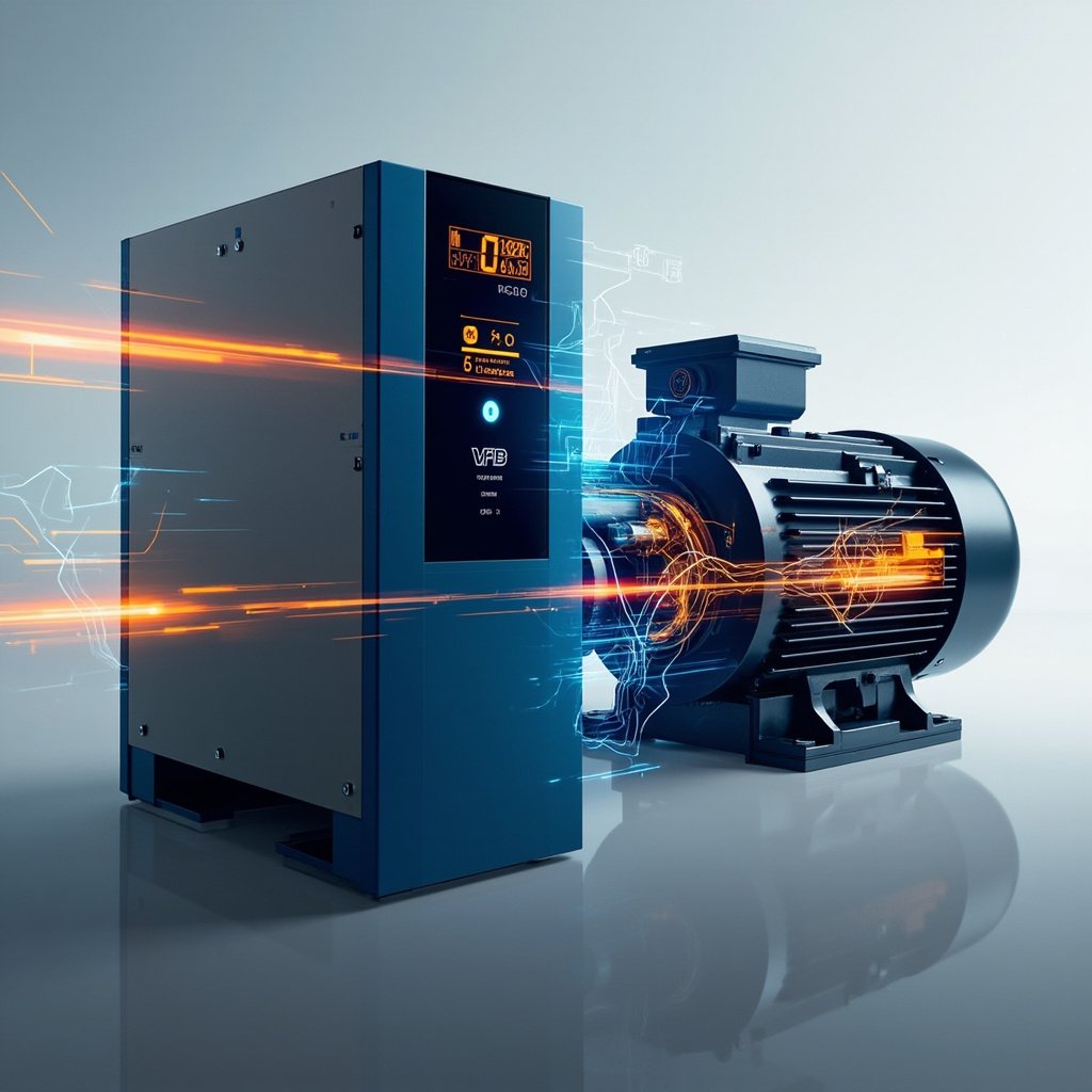
A Variable Frequency Drive (VFD) is one of the most versatile pieces of equipment in modern industrial automation, and among its many programmable parameters, the current limit settings stand out as both critical and frequently misunderstood. Properly configuring the current limit on a VFD protects the motor, the drive itself, and the entire mechanical system from damage caused by excessive current draw. This in-depth guide explores the function, configuration, and best practices for VFD current limit settings, helping technicians, engineers, and facility managers optimize performance while ensuring long-term equipment reliability.
What Is VFD Current Limit and Why Does It Matter?
The VFD current limit is a protective parameter that restricts the maximum output current the drive will deliver to the motor under any operating condition. It functions as a dynamic safeguard: when the load demands more current than the programmed limit, the VFD reduces output frequency or voltage to keep current at or below the threshold. This prevents motor overheating, drive faults, and mechanical stress on connected equipment such as pumps, conveyors, fans, and compressors.
Without proper current limiting, a motor could pull locked-rotor or stall current for extended periods, causing insulation breakdown, bearing failure, or catastrophic winding damage. Similarly, the drive’s IGBT modules and DC bus capacitors can suffer permanent damage from sustained overcurrent events. Setting the current limit correctly is therefore not just a tuning exercise—it is a fundamental part of system protection.
Understanding Current Limit Parameters
Most VFD manufacturers expose current limit through one or more of the following parameter codes, though the exact naming may vary:
- Current Limit (I-Limit): A percentage of the drive’s rated output current, typically adjustable from 0% to 150% or 200%.
- Motor Rated Current (FLA): The full-load amps value of the connected motor, which serves as the reference for current calculations.
- Overload Current: The percentage of rated current allowed for a short duration during starting or transient conditions.
- Overload Time: The maximum duration the overload current can be sustained before the drive trips.
- Current Limit Frequency: The output frequency below which the current limit becomes active, used for low-speed torque boost scenarios.
Typical Default Values Across VFD Brands
While every manufacturer implements current limit slightly differently, the following table summarizes common defaults found in industry-standard drives:
| Manufacturer | Parameter Code | Default Value | Adjustable Range |
|---|---|---|---|
| Allen-Bradley (PowerFlex) | P033 | 110% | 0% – 150% |
| Siemens (Sinamics G120) | P0640 | 150% | 0% – 200% |
| Danfoss (VLT) | 4-18 | 110% | 0% – 150% |
| Yaskawa (A1000) | C1-04 / L8-05 | 150% | 0% – 300% |
| ABB (ACS580) | 2017 / 3017 | 130% | 0% – 200% |
How VFD Current Limit Settings Work
When a VFD detects that output current is approaching or exceeding the programmed limit, the drive’s control algorithm responds in one of several ways depending on the manufacturer and control mode:
- Frequency Reduction: The drive lowers the output frequency, which decreases motor speed and reduces current demand.
- Voltage Reduction: The drive decreases output voltage while holding frequency, which reduces torque and current proportionally.
- Combined V/f Adjustment: Both voltage and frequency are reduced simultaneously to maintain motor stability.
- Fast Trip: If current exceeds the limit for a sustained period, the drive faults and stops output entirely.
In vector control (also known as field-oriented control or FOC), current limiting is more precise because the drive independently controls flux-producing and torque-producing current components. In V/Hz control, the drive approximates current limits through voltage and frequency manipulation, which can be less accurate at low speeds.
Recommended Current Limit Values by Application
Selecting the right current limit depends heavily on the load profile, motor characteristics, and operational priorities. The following recommendations serve as starting points that should be refined based on real-world testing:
| Application Type | Recommended Limit | Rationale |
|---|---|---|
| Centrifugal Pumps | 110% – 120% | Tight limit prevents water hammer and mechanical stress |
| Fans and Blowers | 110% – 130% | Variable torque loads need modest headroom |
| Conveyors | 130% – 150% | Frequent starting and loading demands higher transient capacity |
| Compressors | 120% – 140% | Compensates for high starting torque and load spikes |
| Mixers and Agitators | 140% – 175% | High-viscosity startup can spike current dramatically |
| Crushers and Mills | 150% – 200% | Extreme torque demands require wide current allowance |
⚠️ Important Warning: Never set the VFD current limit above the motor’s service factor ampacity without first confirming the motor’s insulation class, ambient temperature, and duty cycle rating. Setting the limit too high can mask serious mechanical problems such as bearing failure, misaligned couplings, or jammed impellers, leading to catastrophic and costly damage over time. Always pair the current limit with a complementary thermal overload protection model in the VFD.
Step-by-Step Configuration Process
Configuring the current limit on a VFD requires a systematic approach. Follow these steps for accurate setup:
- Verify Motor Nameplate Data: Record the motor’s horsepower, voltage, full-load amps (FLA), service factor, and RPM. This data is the foundation of all current-based parameters.
- Enter Motor Parameters: Input the nameplate FLA into the VFD’s motor rated current parameter. This calibrates the drive’s internal current sensing.
- Run Auto-Tune: If available, perform a static or rotating auto-tune so the VFD learns the motor’s electrical characteristics.
- Set Initial Current Limit: Begin with the manufacturer default (usually 110–150% of FLA) and adjust based on application requirements.
- Configure Overload Time: Match the VFD’s overload time to the motor’s thermal withstand capability, typically 60 seconds for normal duty.
- Test Under Load: Operate the system across its full load range while monitoring actual motor current on the VFD display or via analog output.
- Back to list