

VFD Remote Control Setup: Complete Step-by-Step Guide

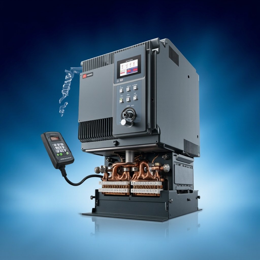
A Variable Frequency Drive (VFD) is the backbone of modern motor control, regulating the speed and torque of AC induction motors across countless industrial and commercial applications. When paired with a remote control setup, a VFD transforms from a simple local panel device into a fully networked component that can be monitored, adjusted, and managed from a distance. Whether you are operating a pump station, an HVAC system, a conveyor line, or a complex manufacturing process, configuring your VFD for remote operation enhances safety, efficiency, and diagnostic capability. This comprehensive guide walks you through the entire process of planning, wiring, configuring, and troubleshooting a VFD remote control setup.
Why Remote Control of VFDs Matters in Modern Industry
Remote VFD control eliminates the need for operators to physically interact with the drive in hazardous or hard-to-reach locations. It allows centralized monitoring of multiple drives from a single supervisory control and data acquisition (SCADA) system, programmable logic controller (PLC), or building management system (BMS). Industries that benefit from VFD remote control include water and wastewater treatment, oil and gas, food and beverage processing, mining, and HVAC systems in large commercial buildings. By enabling real-time data collection, predictive maintenance, and automated response to changing load conditions, remote control dramatically reduces downtime and operational costs.
Core Components of a VFD Remote Control System
Before initiating any setup, you need to gather the necessary hardware and software components. A functional VFD remote control system typically consists of the following elements:
- The VFD unit itself, with digital inputs for run/stop commands and analog or digital inputs for speed reference.
- A communication interface, such as a Modbus RTU module, Profibus card, Ethernet/IP gateway, or built-in industrial Ethernet port.
- Control cabling, including shielded twisted-pair cables for RS-485 networks or Cat5e/Cat6 cables for Ethernet-based protocols.
- A master controller, such as a PLC, industrial PC, HMI panel, or remote terminal unit (RTU).
- Configuration software provided by the VFD manufacturer, used to set parameters, firmware, and network addresses.
- Network infrastructure, which may include routers, switches, wireless access points, and surge protection devices.
Step-by-Step VFD Remote Control Setup Process
Setting up remote control of a VFD requires careful planning and adherence to manufacturer specifications. Follow these structured steps for a reliable installation.
Step 1: Define the Control Objectives
Identify the precise functions you want to control remotely. Common objectives include starting and stopping the motor, adjusting frequency, monitoring current and voltage, retrieving fault logs, and toggling between automatic and manual modes. Document these requirements in a functional specification before contacting the panel builder.
Step 2: Choose the Communication Protocol
The selection of a communication protocol dictates the wiring, addressing, and software configuration. The table below summarizes the most common protocols used for VFD remote control:
| Protocol | Medium | Typical Use Case | Maximum Devices |
|---|---|---|---|
| Modbus RTU | RS-485 twisted pair | Cost-effective serial communication | 32 per segment |
| Modbus TCP | Ethernet (Cat5e/Cat6) | Plant-wide networked drives | Practically unlimited |
| Ethernet/IP | Industrial Ethernet | Integration with Rockwell PLCs | Hundreds per network |
| PROFIBUS DP | RS-485 twisted pair | European manufacturing systems | 126 per segment |
| Profinet | Industrial Ethernet | Siemens-based automation | Hundreds per network |
Step 3: Physical Wiring and Installation
Begin the wiring process by isolating all power sources and verifying zero energy using a properly rated multimeter. Install the communication card or module into the VFD according to the manufacturer manual. Connect the field wiring using shielded cable, grounding the shield at one end only to prevent ground loops. Maintain proper separation between communication cables and power cables, ideally routing them in separate conduit or tray runs. Terminate RS-485 networks with 120-ohm resistors at both ends of the bus to match the characteristic impedance of the cable.
Step 4: Configure VFD Parameters
Configuration parameters vary by manufacturer, but most drives require adjustments in the following areas:
- Command source selection: Set the parameter that determines whether the drive accepts start/stop commands from the local keypad, terminal strip, or communication network.
- Frequency reference source: Select analog input, pulse input, or network register as the source for the speed setpoint.
- Communication address: Assign a unique node ID or IP address to the VFD within the network.
- Baud rate and parity: For serial protocols, configure the data rate to match the master controller (commonly 9600 or 19200 baud).
- Watchdog and fault behavior: Set the timeout value for communication loss and define the drive’s response (coast to stop, ramp to stop, or hold last reference).
- Read/write register mapping: Identify the specific Modbus registers or CIP assemblies used to control outputs and read inputs.
Step 5: Program the Master Controller
Using ladder logic, structured text, or function blocks, program the PLC or controller to send run commands, write frequency references, and poll the drive for status feedback. Modern SCADA systems can be configured using graphical tools that expose VFD parameters as tags. Always test the logic in simulation mode before applying it to a live motor.
Wireless VFD Remote Control Options
In situations where running physical cable is impractical, wireless VFD remote control offers an attractive alternative. Industrial Wi-Fi access points, cellular 4G/5G gateways, and proprietary RF modules can transmit Modbus TCP or vendor-specific protocols over the air. Wireless is particularly useful in mobile equipment, temporary installations, and remote sites such as irrigation pumps and wellhead compressors. However, wireless networks introduce latency, security vulnerabilities, and signal interference that must be addressed through proper antenna placement, encryption, and redundant communication paths.
⚠ Safety Warning: Always lock out and tag out (LOTO) all energy sources before performing any wiring or maintenance on a VFD, even when using a remote interface. Remote commands can unexpectedly start the motor and create serious hazards for personnel working near the equipment. Additionally, configure an emergency stop circuit that is hardwired and independent of the network so that operators can disable the drive in any failure scenario.