Hydraulic Gear Pump Displacement and Pressure Rating Selection: Geroler Gear Type, Volumetric Efficiency, Cavitation Limit

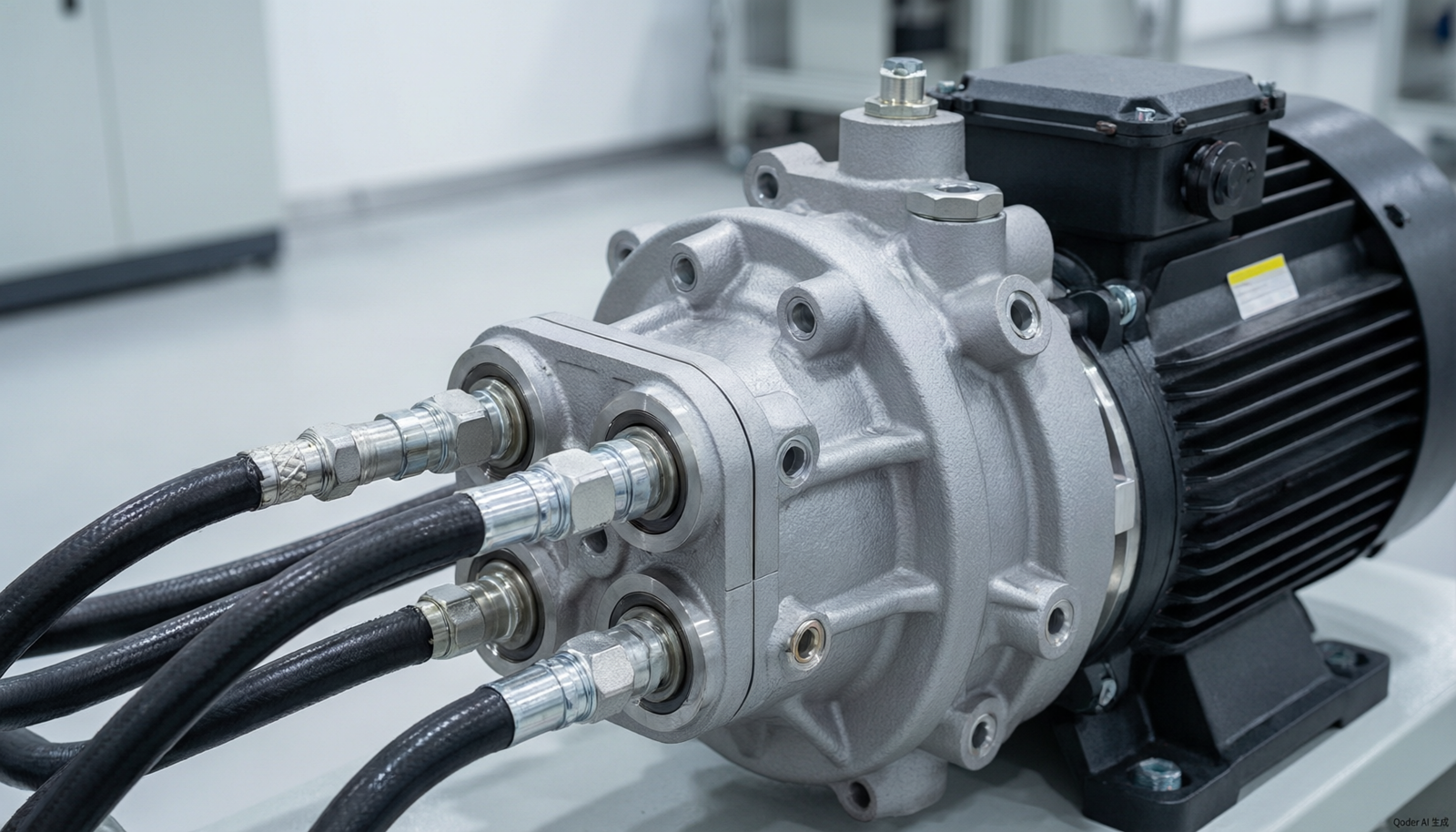
Hydraulic gear pumps are critical components in many industrial automation systems, providing the necessary fluid power to drive machinery and equipment. Selecting the right hydraulic gear pump involves careful consideration of several factors, including displacement, pressure rating, volumetric efficiency, and cavitation limits. This article aims to guide industrial automation engineers through the selection process, focusing on geroler gear type pumps, and provide practical insights into ensuring optimal pump performance.
Introduction
Hydraulic gear pumps are widely used in various applications, from mobile machinery to industrial manufacturing processes. They are favored for their simplicity, reliability, and cost-effectiveness. However, choosing the right pump requires a deep understanding of the system’s requirements and the pump’s technical specifications.
The geroler gear type pump, a variant of the traditional gear pump, offers improved efficiency and quieter operation. This article will explore the key factors in selecting a hydraulic gear pump, with a focus on geroler gear type pumps, and provide guidance on determining the appropriate displacement and pressure rating. We will also discuss the importance of volumetric efficiency and cavitation limits, and how they impact pump performance.
Understanding Hydraulic Gear Pump Displacement
Definition and Importance
Displacement is a fundamental parameter of a hydraulic gear pump, representing the volume of fluid the pump can deliver per revolution. It is typically measured in cubic inches per revolution (in³/rev) or cubic centimeters per revolution (cm³/rev). The displacement directly affects the pump’s flow rate and, consequently, the speed and force of the hydraulic actuators in the system.
Geroler Gear Type Pumps
Geroler gear type pumps are known for their high efficiency and smooth operation. They use an inner rotor and an outer gerotor gear set, which reduces friction and wear, leading to longer service life and lower noise levels. The displacement of a geroler pump can be adjusted by changing the geometry of the gears, allowing for more flexibility in system design.
Calculation of Displacement
The displacement of a geroler gear pump can be calculated using the following formula:
\[ \text{Displacement (D)} = \frac{\pi \times (R^2 – r^2) \times L \times Z}{1000} \]
Where:
- \( R \) = Outer radius of the gerotor (mm)
- \( r \) = Inner radius of the inner rotor (mm)
- \( L \) = Length of the gears (mm)
- \( Z \) = Number of teeth on the inner rotor
For example, if \( R = 50 \) mm, \( r = 40 \) mm, \( L = 30 \) mm, and \( Z = 6 \), the displacement would be:
\[ D = \frac{\pi \times (50^2 – 40^2) \times 30 \times 6}{1000} = 84.82 \text{ cm}^3/\text{rev} \]
Pressure Rating Selection
Understanding Pressure Ratings
The pressure rating of a hydraulic gear pump indicates the maximum pressure the pump can withstand without failing. It is crucial to select a pump with a pressure rating that meets or exceeds the system’s operating pressure to ensure safety and longevity.
Factors Influencing Pressure Rating
Several factors influence the pressure rating of a pump, including:
- Material strength
- Seal type and quality
- Bearing design
- Operating temperature
For instance, a pump with a pressure rating of 3000 psi (207 bar) is suitable for applications where the system pressure does not exceed this value. Exceeding the pressure rating can lead to premature failure of the pump and potential safety hazards.
Selecting the Right Pressure Rating
When selecting a pump, consider the following:
- System Operating Pressure: Determine the maximum pressure the system will experience during operation.
- Safety Factor: Apply a safety factor to account for pressure spikes and transient conditions. A common safety factor is 1.5 to 2 times the operating pressure.
- Pump Type: Different pump types have different pressure capabilities. Geroler gear pumps typically offer higher pressure ratings compared to traditional gear pumps.
Volumetric Efficiency and Cavitation Limits
Volumetric Efficiency
Volumetric efficiency is a measure of the pump’s ability to deliver the theoretical displacement. It is calculated as the ratio of the actual flow rate to the theoretical flow rate, expressed as a percentage. Higher volumetric efficiency indicates better pump performance and reduced energy losses.
Factors affecting volumetric efficiency include:
- Internal leakage
- Fluid viscosity
- Operating temperature
- Wear and tear
Cavitation Limits
Cavitation occurs when the fluid pressure drops below its vapor pressure, causing the formation of vapor bubbles. When these bubbles collapse, they can cause damage to the pump components. Understanding the cavitation limits is crucial to prevent pump damage and ensure reliable operation.
Factors influencing cavitation include:
- Fluid temperature
- Altitude
- Inlet conditions
- Pump speed
Comparison of Hydraulic Gear Pumps
The following table compares different hydraulic gear pumps based on key parameters:
| Parameter | Geroler Gear Pump | Traditional Gear Pump | Gerotor Pump |
|---|---|---|---|
| Displacement Range (cm³/rev) | 10 – 200 | 5 – 150 | 20 – 300 |
| Pressure Rating (psi) | 3000 – 4000 | 2000 – 3000 | 2500 – 3500 |
| Volumetric Efficiency (%) | 85 – 95 | 80 – 90 | 82 – 92 |
| Noise Level (dB) | 60 – 70 | 70 – 80 | 65 – 75 |
| Typical Applications | Industrial machinery, mobile equipment | Automotive, light industrial | Heavy machinery, marine |
Pump Mounting and Shaft Alignment Requirements
Importance of Proper Mounting and Alignment
Proper mounting and shaft alignment are critical to the performance and longevity of hydraulic gear pumps. Incorrect alignment can lead to increased wear, premature failure, and reduced efficiency. This section will discuss alignment tolerance, coupling selection, and common installation mistakes to help engineers ensure optimal pump performance.
Alignment Tolerance
Alignment tolerance refers to the permissible deviation from perfect alignment between the pump shaft and the driver (e.g., electric motor or internal combustion engine). The alignment tolerance is typically specified by the pump manufacturer and is influenced by factors such as:
- Shaft Speed: Higher speed applications require tighter alignment tolerances to minimize vibration and wear.
- Coupling Type: Different coupling types have different tolerance requirements. For instance, flexible couplings can tolerate slight misalignment, while rigid couplings require precise alignment.
- Operating Conditions: Factors such as temperature fluctuations and vibration levels can affect alignment tolerance.
As a general guideline, the alignment tolerance for most hydraulic gear pumps should not exceed 0.001 inches (0.025 mm) of offset and 0.001 inches per inch (0.001 mm/mm) of angular misalignment.
Coupling Selection
Selecting the right coupling is essential for ensuring proper power transmission and accommodating misalignment. Common coupling types for hydraulic gear pumps include:
- Flexible Couplings: These couplings can absorb misalignment and reduce vibration, making them suitable for applications where slight misalignment is unavoidable. Examples include jaw couplings, elastomeric couplings, and grid couplings.
- Rigid Couplings: These couplings provide a solid connection between the pump and driver shafts, requiring precise alignment. They are ideal for applications where misalignment is minimal and high torque transmission is required.
When selecting a coupling, consider the following factors:
- Torque Rating: Ensure the coupling can handle the maximum torque of the pump and driver.
- Speed Rating: Verify that the coupling can operate at the required speed without failure.
- Misalignment Capacity: Choose a coupling that can accommodate the expected misalignment in the system.
Common Installation Mistakes
- Incorrect Shaft Alignment: Misalignment is one of the most common installation errors. It can lead to increased vibration, premature wear, and reduced pump life. Always use precision alignment tools, such as laser alignment systems, to ensure accurate alignment.
- Over-Tightening Mounting Bolts: Over-tightening can cause distortion of the pump housing, leading to internal misalignment and increased wear. Follow the manufacturer’s torque specifications to avoid this issue.
- Inadequate Support: Insufficient support of the pump and driver can result in excessive vibration and stress on the mounting structure. Ensure that the pump and driver are properly supported and anchored to prevent movement.
- Improper Pipe Strain: Pipe strain can introduce forces that affect alignment and increase wear. Use flexible connections and proper pipe support to minimize strain on the pump.
Noise Reduction and Pulsation Damping
Causes of Hydraulic Noise in Gear Pumps
Hydraulic noise in gear pumps is primarily caused by the following factors:
- Fluid Pulsation: The periodic displacement of fluid by the gear teeth creates pressure pulsations, leading to noise.
- Cavitation: As discussed earlier, cavitation can cause noise due to the collapse of vapor bubbles.
- Mechanical Noise: Vibration and mechanical contact between components can also contribute to overall noise levels.
Methods to Reduce Pulsation
- Pressure Relief Valves: Installing pressure relief valves can help regulate system pressure and reduce pulsation by providing a controlled release of excess pressure.
- Flow Dividers: Flow dividers can be used to balance flow and reduce pulsation by dividing the flow into multiple paths.
- Pulsation Dampeners: These devices absorb pressure fluctuations and reduce noise by acting as a buffer between the pump and the system.
Role of Accumulators and Dampeners
Accumulators and dampeners are essential components for noise reduction and pulsation damping in hydraulic systems:
- Accumulators: Accumulators store and release fluid under pressure, helping to smooth out pressure variations and reduce noise. They are particularly effective in systems with high flow rates and pressure fluctuations.
- Dampeners: Dampeners, such as pulsation dampeners and vibration isolators, absorb and dissipate energy from pressure pulses and mechanical vibrations, reducing noise and improving system stability.
Additional Noise Reduction Techniques
- Proper System Design: Designing the hydraulic system with adequate pipe sizing, proper routing, and minimal restrictions can help reduce noise.
- Sound Insulation: Installing sound insulation materials around the pump and other noisy components can help contain and absorb noise.
- Regular Maintenance: Keeping the pump and system components in good condition through regular maintenance can prevent issues that contribute to noise, such as cavitation and mechanical wear.
Conclusion
Proper pump mounting and shaft alignment, along with effective noise reduction and pulsation damping techniques, are essential for ensuring the optimal performance and longevity of hydraulic gear pumps. By following the guidelines outlined in this article, engineers can minimize wear, reduce noise, and enhance the overall efficiency of their hydraulic systems.
For more information on hydraulic system monitoring and related products, visit the Hydraulic System Monitoring Sensor SIKA VT1541MSIPS0A4 page. Additionally, explore the Vacuum Pump Repair Kit Leybold EK110002668 and Rexroth 0608 PE0-283 983000011 Gearbox for Automation for insights into maintaining and optimizing your hydraulic systems.
Call to Action
Explore our extensive catalog of hydraulic components and systems to find the perfect solution for your industrial automation needs. Whether you’re looking for sensors, pumps, or gear reducers, we have the products to meet your requirements. Visit our product catalog to browse and discover more.
FAQ
1. What is the difference between geroler and gerotor pumps?
Geroler pumps use an inner rotor and an outer gerotor gear set, while gerotor pumps use a single gerotor gear set. Geroler pumps generally offer higher efficiency and lower noise levels.
2. How do I determine the appropriate pressure rating for my application?
Determine the maximum system pressure and apply a safety factor of 1.5 to 2 times the operating pressure to account for pressure spikes and transient conditions.
3. What factors affect the volumetric efficiency of a hydraulic gear pump?
Internal leakage, fluid viscosity, operating temperature, and wear and tear are the main factors affecting volumetric efficiency.
4. Can cavitation damage hydraulic gear pumps?
Yes, cavitation can cause significant damage to pump components due to the collapse of vapor bubbles, leading to reduced pump life and potential failure.
5. How can I prevent cavitation in my hydraulic system?
Ensure proper inlet conditions, maintain adequate fluid temperature, and design the system to avoid low-pressure zones that can lead to cavitation.
Conclusion
Selecting the right hydraulic gear pump involves a comprehensive understanding of the system’s requirements and the pump’s technical specifications. By considering factors such as displacement, pressure rating, volumetric efficiency, and cavitation limits, engineers can ensure optimal pump performance and longevity.
For more information on hydraulic system monitoring and related products, visit the Hydraulic System Monitoring Sensor SIKA VT1541MSIPS0A4 page. Additionally, explore the Vacuum Pump Repair Kit Leybold EK110002668 and Rexroth 0608 PE0-283 983000011 Gearbox for Automation for insights into maintaining and optimizing your hydraulic systems.
Call to Action
Explore our extensive catalog of hydraulic components and systems to find the perfect solution for your industrial automation needs. Whether you’re looking for sensors, pumps, or gear reducers, we have the products to meet your requirements. Visit our product catalog to browse and discover more.