

Rexroth IndraDrive Servo Parameter Configuration: Drive Bus Setup, Motor Commissioning, Control Loop Tuning, Diagnostic Parameter

Introduction
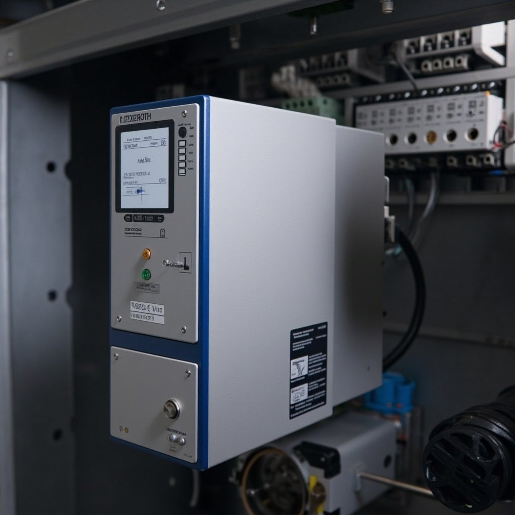
In the realm of industrial automation, the performance of servo drives is paramount to the efficiency and precision of machinery in applications ranging from CNC machines to packaging equipment and material handling systems. Proper configuration of servo drive parameters is not merely a technical prerequisite but a critical factor that directly influences the motion control performance and overall machine throughput. The Rexroth IndraDrive series, known for its robustness and versatility, offers a comprehensive suite of features that, when optimally configured, can significantly enhance the operational capabilities of automated systems. This article provides a detailed guide on the systematic configuration of Rexroth IndraDrive servo drives, covering essential aspects such as drive bus setup, motor commissioning, control loop tuning, and diagnostic parameters. By following this guide, automation engineers and drive technicians can ensure that their systems operate at peak performance, thereby maximizing productivity and reliability.
Related Products:
Rexroth HMD01.1N-W0020 Servo Drive, Rexroth SE352 Servo Drive Control, Rexroth 3C-ET-ENS Encoder Card
Rexroth IndraDrive Product Range Overview
The Rexroth IndraDrive series is a versatile family of servo drives designed to meet the diverse needs of modern automation applications. The series includes models such as the HMD01, HCS01, and HCS03, each offering varying power ratings from 2kW to 280kW. These drives are available in both single-axis and multi-axis configurations, providing flexibility for a wide range of applications. The HMD01 series, for instance, is particularly suited for high-performance applications requiring precise control and rapid response times. The IndraDrive series supports various communication protocols, including SERCOS III, EtherCAT, and PROFINET, ensuring seamless integration into different automation environments.
SERCOS Drive Bus Communication Setup
SERCOS III Ring Topology
The SERCOS III protocol is a high-performance communication standard widely used in industrial automation for its deterministic and real-time capabilities. The IndraDrive series supports the SERCOS III protocol, which utilizes a ring topology to ensure redundancy and fault tolerance. In a SERCOS III network, each drive acts as a node, and the network is configured in a ring, allowing data to travel in both directions. This configuration ensures that if one path fails, the data can still reach its destination via the alternate path.
Node Address Assignment
Each IndraDrive in a SERCOS III network must be assigned a unique node address. This address is crucial for the master controller to identify and communicate with individual drives. The node address can be set via the drive’s control panel or through the engineering software provided by Rexroth.
Communication Cycle Time
The communication cycle time is a critical parameter that determines the frequency at which data is exchanged between the master controller and the drives. For high-performance applications, a shorter cycle time is desirable to ensure rapid response and precise control. The IndraDrive series supports cycle times as low as 250 microseconds, making it suitable for applications requiring high-speed communication.
Telegram Configuration
Telegram configuration involves setting up the data packets that are exchanged between the master controller and the drives. This includes defining the types of data to be transmitted, such as position commands, velocity commands, and feedback data. Proper telegram configuration is essential for ensuring that the correct data is exchanged in a timely manner.
Master-Slave Synchronization
In a SERCOS III network, the master controller synchronizes the communication with all the drives. This synchronization ensures that all drives operate in a coordinated manner, which is crucial for applications requiring precise coordination between multiple axes. The IndraDrive series supports advanced synchronization features, allowing for highly coordinated motion control.
Motor Commissioning Procedure
Motor Type Selection
The first step in commissioning a motor with an IndraDrive is to select the correct motor type. This involves specifying the motor’s technical parameters, such as the nominal power, nominal speed, and nominal torque. The IndraDrive series supports a wide range of motor types, including synchronous and asynchronous motors.
Encoder Configuration
Encoder configuration involves setting up the feedback device that provides position and speed information to the drive. The Rexroth 3C-ET-ENS Encoder Card is a popular choice for this purpose, offering high-resolution feedback and robust performance. Proper encoder configuration is essential for ensuring accurate position and speed control.
Commutation Angle Adjustment
The commutation angle is a critical parameter that affects the motor’s torque production and efficiency. Adjusting the commutation angle ensures that the motor operates at optimal efficiency and produces the required torque. This adjustment is typically performed during the initial commissioning of the motor.
Standstill Current
The standstill current is the current drawn by the motor when it is at rest. Setting the correct standstill current is important for preventing overheating and ensuring that the motor remains within its thermal limits. The IndraDrive series allows for precise control of the standstill current, ensuring safe and reliable operation.
Motor Thermal Model Parameter
The motor thermal model parameter is used to predict the motor’s temperature rise during operation. This parameter is crucial for implementing thermal protection and preventing overheating. The IndraDrive series includes advanced thermal modeling capabilities, allowing for accurate prediction and control of the motor’s temperature.
Position and Velocity Control Loop Tuning
Speed Controller P-Gain and I-Time
The speed controller’s P-gain and I-time are critical parameters that determine the controller’s response to changes in speed commands. The P-gain affects the controller’s sensitivity to errors, while the I-time determines the rate at which the controller corrects these errors. Proper tuning of these parameters is essential for achieving stable and responsive speed control.
Position Loop Gain
The position loop gain determines the controller’s response to changes in position commands. A higher gain results in a more responsive system, but too high a gain can lead to instability. The IndraDrive series allows for precise adjustment of the position loop gain, ensuring optimal performance.
Feedforward Parameter
The feedforward parameter is used to improve the system’s response to rapid changes in commands. By anticipating the required changes, the feedforward parameter can enhance the system’s dynamic performance. Proper configuration of this parameter is crucial for applications requiring rapid and precise motion.
Load Inertia Identification
Accurate identification of the load inertia is important for achieving optimal control performance. The IndraDrive series includes tools for identifying the load inertia, allowing for precise tuning of the control parameters.
Auto-Tuning Function
The auto-tuning function automates the process of tuning the control loops, making it easier to achieve optimal performance. This function analyzes the system’s response and adjusts the control parameters accordingly, saving time and ensuring consistent results.
Diagnostic Parameter and Fault Management
P-0-0000 Parameter Structure
The P-0-0000 parameter structure is a comprehensive framework for accessing and configuring diagnostic parameters. This structure includes parameters for monitoring various aspects of the drive’s operation, such as temperature, current, and voltage.
Oscilloscope Function
The oscilloscope function provides real-time visualization of the drive’s signals, allowing for detailed analysis and troubleshooting. This function is invaluable for diagnosing issues related to signal integrity and timing.
Fault Code Interpretation
The IndraDrive series includes a comprehensive set of fault codes that provide detailed information about any issues that arise. Understanding these codes is crucial for effective fault management and troubleshooting.
Travel Profile Monitoring
Travel profile monitoring involves tracking the motor’s movement and comparing it to the commanded profile. This monitoring helps identify any discrepancies or issues related to the motion control system.
Torque Limit Configuration
Configuring the torque limits ensures that the motor operates within its safe operating range. The IndraDrive series allows for precise configuration of these limits, providing protection against overload and ensuring reliable operation.
Comparison Table: Rexroth IndraDrive vs Competing Servo Drives
| Feature | Rexroth IndraDrive | Siemens SINAMICS S120 | ABB ACSM1 | Beckhoff AX8000 |
|---|---|---|---|---|
| Communication Protocol | SERCOS III, EtherCAT, PROFINET | PROFINET, EtherCAT, EtherNet/IP | EtherCAT, Modbus TCP, PROFINET | EtherCAT, PROFINET, EtherNet/IP |
| Tuning Method | Auto-tuning, Manual Tuning | Auto-tuning, Manual Tuning | Auto-tuning, Manual Tuning | Auto-tuning, Manual Tuning |
| Safety Functions | STO, SS1, SS2, SLS, SLP | STO, SS1, SLS, SLP | STO, SS1, SLS, SLP | STO, SS1, SLS, SLP |
| Diagnostic Capability | Advanced Oscilloscope, Fault Code Interpretation, Travel Profile Monitoring | Advanced Oscilloscope, Fault Code Interpretation | Basic Oscilloscope, Fault Code Interpretation | Advanced Oscilloscope, Fault Code Interpretation |
FAQ
1. What is the minimum communication cycle time supported by the IndraDrive series?
The IndraDrive series supports a minimum communication cycle time of 250 microseconds, ensuring high-speed communication and rapid response.
2. Can the IndraDrive series be integrated with non-Rexroth motors?
Yes, the IndraDrive series can be configured to work with a wide range of motor types, including those from other manufacturers, provided they meet the necessary specifications.
3. How does the auto-tuning function work?
The auto-tuning function analyzes the system’s response to changes in commands and automatically adjusts the control parameters to achieve optimal performance. This process simplifies the tuning process and ensures consistent results.
Conclusion
Configuring the parameters of a Rexroth IndraDrive servo drive is a critical task that can significantly impact the performance and reliability of automated systems. By following the guidelines outlined in this article, engineers and technicians can ensure that their drives are optimally configured for their specific applications. The IndraDrive series offers advanced features and capabilities that, when properly utilized, can enhance the efficiency and precision of motion control systems. For more information on Rexroth IndraDrive products, visit the Rexroth HMD01 and Rexroth SE352 product pages.
Call to Action: For further assistance with Rexroth IndraDrive configuration or to explore our range of servo drives, contact our technical support team or browse our product catalog.