

Braking Unit Capacity Calculation: A Complete Technical Guide

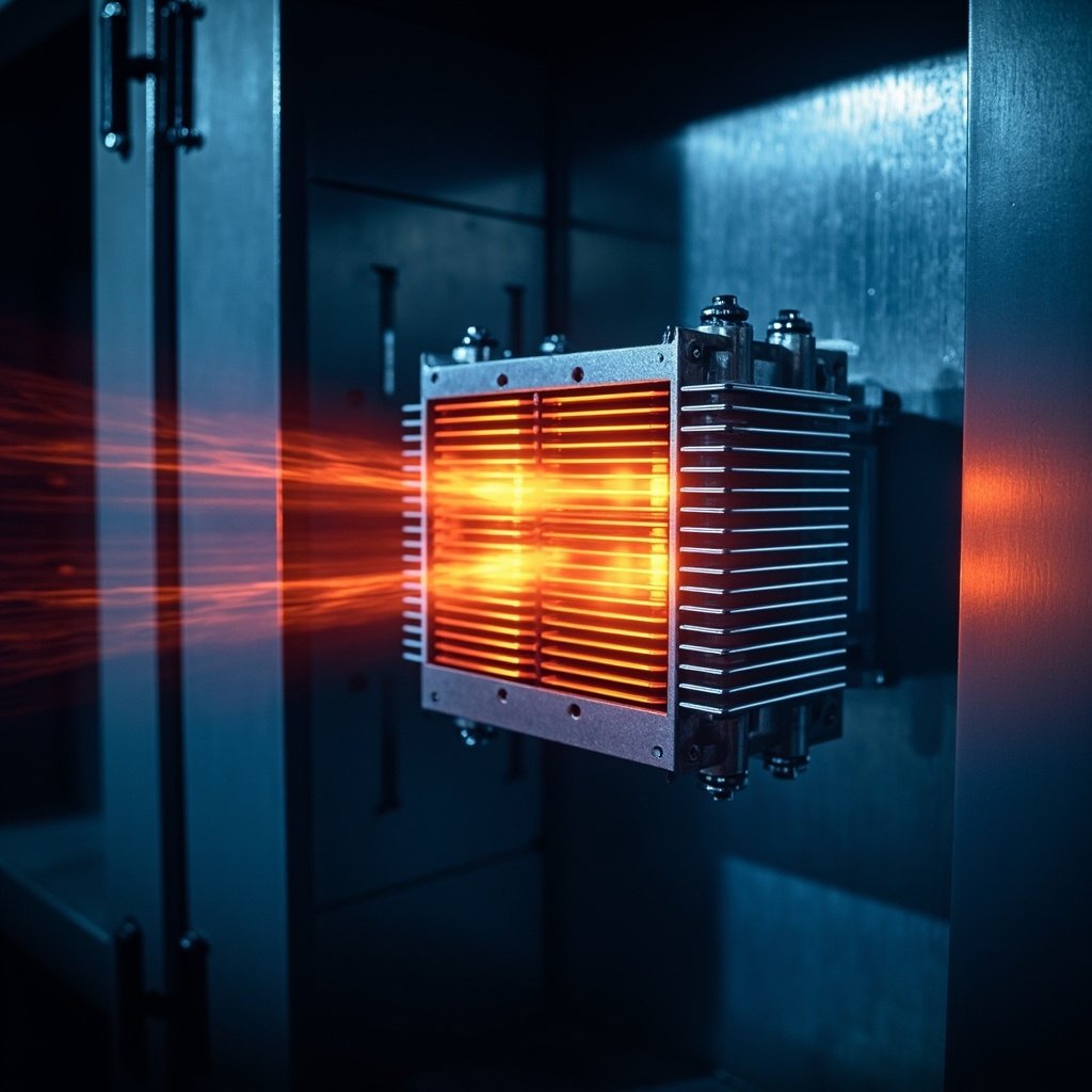
Accurately determining the braking unit capacity is one of the most critical engineering tasks in modern motion control and variable frequency drive (VFD) systems. Whether you are designing a high-inertia hoist, a regenerative conveyor, or a precision elevator, the ability of the braking resistor and braking unit to absorb kinetic energy safely directly impacts system reliability, downtime, and component lifespan. An undersized braking unit can lead to DC bus overvoltage trips, catastrophic resistor failure, or even fire hazards, while an oversized one increases cost and footprint unnecessarily. This guide walks you through every aspect of braking unit capacity calculation, blending engineering theory with practical field-tested formulas.
What Is a Braking Unit and Why Capacity Matters
A braking unit (also called a brake chopper or regenerative braking module) is an electronic switching device connected between the DC bus of a drive and an external braking resistor. When the motor acts as a generator during deceleration or overhauling loads, the kinetic or potential energy flows back into the DC bus, raising the voltage. The braking unit senses this rise and switches on, dumping the excess energy into the resistor as heat.
The capacity of this system is defined by two interrelated ratings: peak power (instantaneous dissipation capability) and continuous/average power (long-term thermal handling). Getting both right is the essence of proper braking unit capacity calculation.
Key Parameters Used in the Calculation
Before plugging numbers into any formula, gather the following system data. Skipping this step is the #1 cause of failed installations.
| Parameter | Symbol | Typical Unit | Source |
|---|---|---|---|
| Total moving mass / inertia | J or m | kg·m² or kg | Mechanical drawing |
| Initial / operating speed | v or ω | m/s or rad/s | Process specification |
| Deceleration time | t | seconds | Drive ramp setting |
| Duty cycle / braking frequency | D | % per minute | Application profile |
| DC bus trip voltage | V_dc | Volts (e.g., 750 V) | Drive manual |
| Brake resistor value | R | Ohms | Manufacturer datasheet |
Step-by-Step Braking Unit Capacity Calculation
Follow this proven four-step workflow used by drive integrators worldwide.
- Step 1 – Calculate total regenerative energy. For a rotating system: E = ½ · J · ω². For a linear load: E = ½ · m · v². Don’t forget to add the motor’s own rotor inertia reflected to the load.
- Step 2 – Convert energy into peak power. Peak power is the energy divided by the deceleration time: P_peak = E / t. This is the minimum instantaneous dissipation your resistor must handle.
- Step 3 – Apply the duty cycle to find continuous power. P_continuous = P_peak × (t_brake / t_cycle). This is the value the resistor must sustain thermally without exceeding its temperature rise rating.
- Step 4 – Verify resistor Ohm value. R_min = V_dc² / P_peak. Choose the next standard resistor value above this minimum to allow safe IGBT switching headroom.
Worked Example: Vertical Lift Application
Imagine a 1,200 kg cabin descending at 1.5 m/s, deceleration time 3 s, with 4 stops per minute. Let’s run the braking unit capacity calculation:
- Kinetic energy: E = ½ × 1,200 × 1.5² = 1,350 J
- Peak power: P_peak = 1,350 / 3 = 450 W
- Cycle time = 60 s / 4 = 15 s, so duty factor = 3 / 15 = 0.2
- Continuous power: P_cont = 450 × 0.2 = 90 W
- With V_dc = 750 V, R_min = 750² / 450 ≈ 1,250 Ω
Select a 1.5 kΩ, 150 W resistor – comfortably covering both peak and continuous needs.
Comparison of Common Braking Resistor Types
| Resistor Type | Pulse Withstand | Typical Use | Cost Level |
|---|---|---|---|
| Wire-wound aluminum housed | High (10× for 5 s) | General VFD, hoists | $ |
| Stainless steel grid | Very high (20× for 10 s) | Cranes, elevators, mining | $$ |
| Thick-film flat | Moderate (3–5×) | Compact drives, light duty | $ |
| Liquid-cooled (water/glycol) | Extreme (>50×) | High-power regenerative, marine | $$$ |
Common Pitfalls in Braking Unit Capacity Calculation
Even experienced engineers make these mistakes. Watch out for:
- Forgetting gear ratios – J_load reflected to the motor shaft is J_load / n², which dramatically changes ω.
- Confusing power ratings – A resistor labeled “500 W” is usually continuous. Confirm pulse ratings with the manufacturer’s graphs.
- Ignoring gravity – In vertical applications, gravitational potential energy (mgh) is added to kinetic energy, often doubling the total.
- Overlooking ambient temperature – Resistors de-rate above 40 °C; multiply continuous power by 1.25 for every 10 °C above.
- Neglecting cable inductance – Long resistor cables can cause voltage spikes; keep runs under 10 m or use twisted pairs.
⚠ Safety Warning: Braking resistors can reach surface temperatures above 300 °C. Always mount them on non-combustible surfaces, provide adequate clearance (≥ 200 mm from cabling), integrate a thermal fuse, and ensure the enclosure has forced ventilation or fire-rated shielding. Never bypass the brake chopper’s enable signal – it is the primary protection against DC bus runaway.
Advanced Considerations: Regenerative vs. Resistive Braking
When energy recovery is more important than cost, an active front end (AFE) or regenerative drive can feed power back to the grid instead of dissipating it as heat. In these cases, the braking unit capacity calculation shifts from thermal sizing to harmonics compliance (IEEE 519) and transformer coordination. However, a small line-side filter resistor is still recommended for fault-ride-through, and the